The Physics of Nerve Stimulation and Nerve Impedance
Philip C. Cory
For decades, anesthesiologists have been using equipment for nerve stimulation that is nonoptimal. The following is a discussion of the physics and electronics involved in nerve stimulation.
Requirements for nerve depolarization
Neuronal depolarization by externally applied electrical fields requires a cathodal transmembrane voltage gradient in the range of 6 to 7 mV.1 In his authoritative chapter, Hille2 states, “The conducTance changes apparently depend only on voltage and not on the direction or magnitude of current flow [italics added].” An electric field strength of 100 mV/cm is required to achieve such a transmembrane gradient for neurons longer than five times their length consTant (approximately 5×1 mm).3 This cathodal gradient distorts the voltagesensing fourth region (S4) of sodium channel membrane-spanning segments to effect pore opening. As positive charges on the S4 region move toward the extracellular side of the membrane, an outwardly directed gating current occurs followed by the inwardly directed current associated with sodium ions moving from extracellular to intracellular.4 This gating current is not bulk ion flow associated with the voltage gradient. It is the movement in space of the charged moieties on the S4 region.
Coulomb’s Law
Coulomb’s law of electrostatics (eq. 1) defines forces between two immobile charges in space, describing neither current flow nor current effects at a disTance.

This relationship states that the force (F, or electric intensity in V/m) between two static charges (q1 and q2) is inversely related to the disTance (r) between the charges and the permittivity of free space (ε0). ImporTantly, F is not current; it is voltage per unit disTance. The significant concept emerging from Coulomb’s law is that voltage gradients are established without need for charge movement in space (i.e., current flow). The converse is not true; for current to flow, charges must move along a voltage gradient. This is a critical concept for undersTanding nerve stimulation.
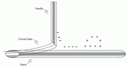
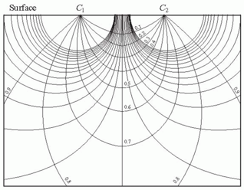
A voltage gradient between two points in a bulk conductor of uniform composition causes current flow at right angles to the semicircular equipotential lines of force as shown in Figure 3.1.5 No static charge will accumulate in such a situation. In Figure 3.2, a mixture of positive and negative charges arises because there are regions of differing conductivity
and paths of preferential current flow because tissue is best described as nonhomogeneous and anisotropic.
and paths of preferential current flow because tissue is best described as nonhomogeneous and anisotropic.
Impedance
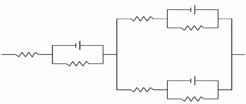
Tissue voltage/current electrical response is not just resistive as in Ohm’s law (E = IR); it displays an impedance, comprising resistive and capacitive components arranged in series and in parallel (RC circuit), as shown in Figure 3.3. Electrical impedance is a measure of opposition to time-variant electric current. The time function of impedance is imporTant to alternating current waveforms. Anesthesia nerve stimulators, with duty cycles (the ratio of the pulse being “on” to that of it being “off”) of 1:9,999 at 1 Hz with a 100 µs pulse width, do not produce time-variant waveforms. When such square current pulses are applied to a
resisTance, square voltage pulses result; however, when the same current pulse is applied to an impedance, a voltage charging curve is seen that reflects resisTance and reacTance. ResisTance is fixed opposition to current regardless of time or waveform considerations, but reacTance varies with the waveform (i.e., it reacts to the electrical field). Impedance, resisTance, and capacitive reacTance are related in eq. 2,
resisTance, square voltage pulses result; however, when the same current pulse is applied to an impedance, a voltage charging curve is seen that reflects resisTance and reacTance. ResisTance is fixed opposition to current regardless of time or waveform considerations, but reacTance varies with the waveform (i.e., it reacts to the electrical field). Impedance, resisTance, and capacitive reacTance are related in eq. 2,
 Figure 3.2. STandard nerve stimulation depiction showing negative charge accumulation inducing an anodal surround. |

where Z is impedance, f is frequency, and C is capaciTance in farads.
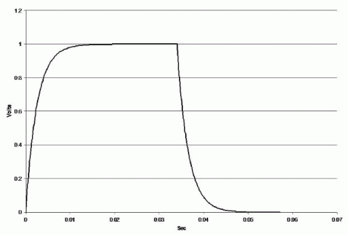
Current, when introduced into a parallel RC circuit, initially distributes charge onto capacitive surfaces. Very shortly after current flow initiation, the repulsive action of accumulating charge on capacitive surfaces shunts current through the resisTance of the RC circuit. As a progressively larger proportion of the charge flows through the resisTance, the voltage differential across the circuit increases in an exponential fashion. When the current pulse is stopped, the voltage falls in an exponential fashion; the complete curve is shown in Figure 3.4.
 Figure 3.4. Charge/discharge curve for an RC circuit with R = 2,500Ω, C = 1.0 × 10⁻⁶F and a 34-msec direct current pulse. |
Direct current cannot flow through a capacitor; when the capacitive surfaces are fully charged, the current flows entirely through the resistive limb of the circuit, determining the final voltage value. The charging portion of the curve is described by eq. 3,

where V0 is the final voltage, Vi is the initial voltage, t is time in seconds, and τ is the circuit time consTant equal to R × C. The discharge curve is described by eq. 4,

Stay updated, free articles. Join our Telegram channel

Full access? Get Clinical Tree


