The Anesthesia Machine
Adeola O. Sadik
Gregory Ginsburg
I. OVERVIEW
The basic function of the anesthesia machine is to prepare a gas mixture of precisely known and variable composition for delivery to the patient. The machine delivers a controlled flow of oxygen, nitrous oxide, air, and anesthetic vapors. These are delivered to a breathing system, which provides a means to deliver positive-pressure ventilation and to control alveolar carbon dioxide by minimizing rebreathing and/or by absorbing exhaled carbon dioxide. A mechanical ventilator is connected to the breathing system, freeing the anesthetist’s hands for other tasks. Various monitors are used to survey the functioning of the ventilation system, to detect equipment malfunctions, and to provide information about the patient.
II. THE GAS DELIVERY SYSTEM (FIG. 9.1)
A. Gas Supplies
1. Piped gases. Wall outlets deliver oxygen, nitrous oxide, and air, from a central supply source, at a pressure of 50 to 55 pounds/in2 (psi). These outlets and the supply hoses to the machine are diameter indexed and color coded in order to safeguard against the administration of a hypoxic gas mixture.
2. Cylinders. Gas cylinders are used as backup sources when wall delivery fails or in locations where piped anesthesia gases are not available. Anesthesia machines use the size E cylinder. In a similar fashion to the gas supply hoses, cylinder colors are specific for each gas and pin indexed to prevent connection to the wrong regulator. It is important to make sure that each anesthesia machine has a cylinder wrench to enable the flow of gas when piped gases are not available.
a. A full cylinder of oxygen (green) has a pressure of 2,000 to 2,200 psi and contains the equivalent of 660 L of gas at atmospheric pressure and room temperature. The oxygen cylinder pressure decreases in direct proportion to the amount of oxygen remaining in the cylinder.
b. A full cylinder of nitrous oxide (blue) has a pressure of 745 psi and contains the equivalent of 1,500 L of gas at atmospheric pressure and room temperature. The nitrous oxide in the full cylinder is primarily in the liquid phase; the cylinder pressure does not decrease until the liquid content is exhausted, at which time approximately one fourth of the total volume of gas remains.
c. Air cylinders are present on some machines. A full cylinder (yellow) has a pressure of 1,800 psi and contains the equivalent of 630 L at atmospheric pressure and room temperature.
d. Pressure regulators reduce the high pressure from the cylinders to about 45 psi (just below pipeline pressure) so that, when cylinder gases are used, adjustments at the flow valves (rotameters) are not needed to compensate for the changing pressure that occurs as the cylinders empty. If both cylinders and pipelines are connected and open, gas flows preferentially from the pipeline because its pressure is slightly higher than the regulated cylinder pressure.
The regulators divide the machine into high-pressure (proximal to the regulator) and low-pressure (distal to the regulator) systems. In the event that the pipeline pressure fails or is less than the cylinder pressure, the cylinder will supply the gas until it is emptied.
The regulators divide the machine into high-pressure (proximal to the regulator) and low-pressure (distal to the regulator) systems. In the event that the pipeline pressure fails or is less than the cylinder pressure, the cylinder will supply the gas until it is emptied.
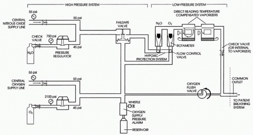 FIGURE 9.1 Schematic of an anesthesia machine. There are many variations in the design depending on vintage and manufacturer. |
B. Flow control valves and flowmeters control and measure gas flows.
1. A needle valve controls the flow of each gas. As a safety feature, the oxygen control knob has a different texture and, occasionally, protrudes more than the nitrous oxide and air controls. The needle valves also reduce gas pressures from 45 to 55 psi (high pressure) to near atmospheric pressure (low pressure).
2. Flowmeters. The traditional flowmeter is a calibrated tapered glass tube in which a bobbin or a ball float is used to indicate the flow of gas. Flowmeters with a ball float should be read in the middle of the ball. Meters with a bobbin should be read at the top of the bobbin. Newer anesthesia machines have electronic flowmeters and displays that often provide a digital readout. The oxygen flowmeter is always placed downstream so that a leak will be less likely to result in delivery of a hypoxic gas mixture.
C. Vaporizers. Anesthesia machines are outfitted with one or more temperature-compensated flow-over vaporizers calibrated to deliver a specific concentration of anesthetic measured as percent by volume. These vaporizers operate on the principle that a small proportion of the total gas mixture delivered to them is diverted into a vaporizing chamber, where it becomes fully saturated with anesthetic before it is added back to the main flow. The concentration of anesthetic delivered by the vaporizer is therefore proportional to the amount of gas passing through the vaporizing chamber, which is controlled primarily by the vaporizer dial. Because saturated vapor pressure varies with temperature, a secondary mechanism alters the amount of gas diverted through the chamber to compensate for temperature changes. The vaporizers are calibrated for a specific anesthetic and have pin-indexed filling adapters to prevent inadvertent addition of an incorrect anesthetic to a vaporizer. The vaporizing chamber is enclosed in a metal case to enhance heat transfer and to compensate for the heat lost from cooling as the anesthetic evaporates. The desflurane vaporizer is heated and pressurized to compensate for the anesthetic’s relatively high vapor pressure and the extreme cooling that occurs when high concentrations are vaporized.
D. The Common Gas Outlet is the port where gases exit the machine; it is connected to the breathing system via the fresh gas hose.
E. Oxygen Flush Valve. One hundred percent oxygen at 45 to 55 psi comes directly from the high-pressure system to the common gas outlet. Oxygen flow can be as high as 40 to 60 L/minute. Caution should be taken when using this valve for intubated patients in order to prevent barotrauma.
III. BREATHING SYSTEMS
The circle system is most commonly used. The T-piece systems (Mapleson D and F) are used in infants because of low resistance and small dead space.
A. The Circle System. The circle system incorporates a carbon dioxide absorber and prevents rebreathing of exhaled carbon dioxide. The system allows low fresh gas flows that conserve use of expensive inhalation anesthetics and maintain higher humidity and temperature within the breathing circuit. The circle consists of an absorber, two one-way valves, a Y-piece adapter, a reservoir bag, and an adjustable pressure limiting (APL) “pop-off” valve (Fig. 9.2).
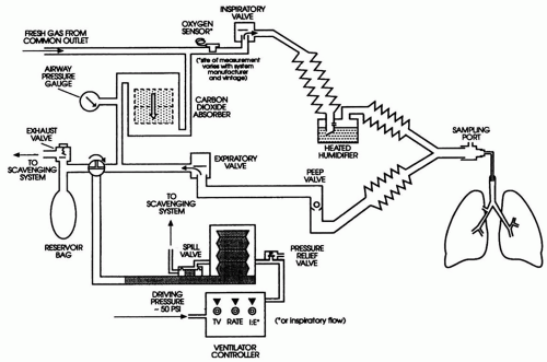 FIGURE 9.2 Representative circle breathing system with ventilator. The airway pressure gauge may sense on the patient side of the inspiratory valve. The PEEP valve may be integral to the ventilator. Other variations are possible depending on the manufacturer. |
1. The carbon dioxide absorber. Soda lime (CaOH2 + NaOH + KOH + silica) or Baralyme (Ba[OH]2 + Ca[OH]2) contained in the absorber combines with carbon dioxide, forming CaCO2 and liberating heat and moisture (H2O). A pH-sensitive dye changes to blue-violet, indicating exhaustion of the absorbing capacity. In older machines with a two-tiered canister system, the top canister should be changed when 25% to 50% of the pellets have changed color, although a second canister provides a safety margin. The size of the container used should accommodate a patient’s tidal volume for maximum efficiency.
2. Two one-way valves (inspiratory and expiratory) ensure that exhaled gas is not rebreathed without passing through the carbon dioxide absorber.
3. The Y-piece adapter is used to connect the inspiratory and expiratory sides of the system to the patient.
4. The reservoir bag and APL valve are located on the expiratory limb. The reservoir bag accumulates gas between inspirations. It is used to visualize spontaneous ventilation and to assist ventilation manually. Typically, a 3 L reservoir bag is used for adult patients; smaller bags may be appropriate for pediatric patients. The APL valve is used to control the pressure in the breathing system and allows excess gas to escape. The valve can be adjusted from fully open (for spontaneous ventilation, minimal peak pressure 1 to 3 cm H2O) to fully closed (maximum pressure 75 cm H2O or greater). Dangerously high pressures that may produce barotrauma and hemodynamic compromise can occur if the valve is left unattended in the fully or partially closed position.
B. The T-Piece Systems. The T-piece systems are single-limbed rebreathing systems. Because there is no CO2 absorber, rebreathing of CO2 is inevitable unless a fresh gas flow at least equal to the patient’s peak flow is used. Inspired CO2 concentration is controlled by the fresh gas flow and/or by varying the minute ventilation. Mapleson classified all possible configurations of single-limbed rebreathing systems (the T-pieces included) according to the relative position of the patient, fresh gas flow, reservoir bag, and valve. The Mapleson D and F systems are used most frequently and are both T-piece systems. All the T-piece systems require high fresh gas flows (at least two to three times minute ventilation) to prevent rebreathing during spontaneous ventilation. Capnography is useful to verify sufficient washout of carbon dioxide.
1. The Mapleson D circuit is a semiclosed system with a reservoir bag and APL valve at the machine end with fresh gas entering at the patient end (Fig. 9.3).
Related posts:


Stay updated, free articles. Join our Telegram channel

Full access? Get Clinical Tree


