Fig. 18.1
S2–3 Retrograde: L2–3 epidural “lateral” approach (anteroposterior [AP] view)
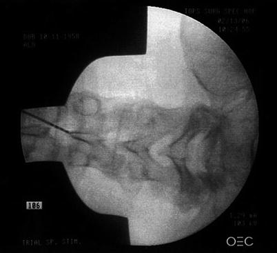
Fig. 18.2
S2–3 Retrograde: L2–3 needle tip in steep caudal view to limit hand exposure
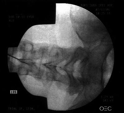
Fig. 18.3
S2–3 Retrograde: electrode directed caudally in the midline
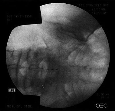
Fig. 18.4
S2–3 Retrograde: electrode crossing S1 level in midline
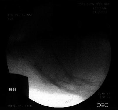
Fig. 18.5
S2–3 Retrograde: S1 level electrode posterior on lateral view
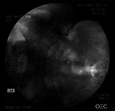
Fig. 18.6
S2–3 Retrograde: electrode rotated to right S2–3 foramen: stimulating right S2–4 roots
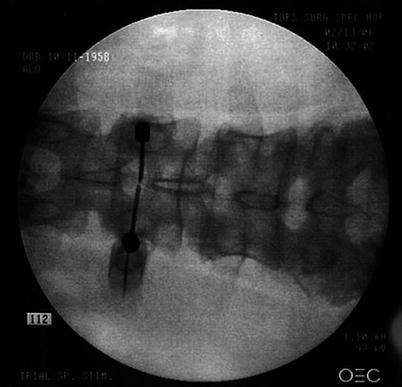
Fig. 18.7
S2–3 Retrograde: dual L2–3 epidural “lateral” approach (AP view)
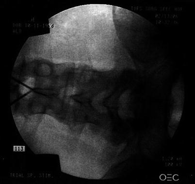
Fig. 18.8
S2–3 Retrograde: dual L2/3 needle tips in steep caudal view to limit hand exposure
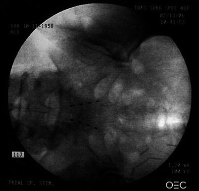
Fig. 18.9
S2–3 Retrograde: dual electrodes at final S2–3 foramen stimulating S2–4 roots
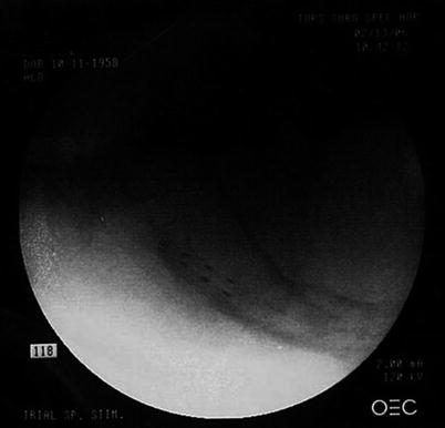
Fig. 18.10
S2–3 Retrograde: dual electrodes at S2–3 stimulating S2–4 roots (lateral view)
18.2 Technical Overview
18.2.1 Cephalocaudal Lumbosacral Electrode Placement: Foot and Pelvic Root Placement
To stimulate the foot, a quadrapolar electrode enters the midline at L2–3 crossing over the L3–4 disc space before it is then rotated to, but not through, the L4 foramen (Figs. 18.11 and 18.14). This positioning allows the electrode to remain “in line” with the ipsilateral L4, L5, and S1 roots. It is then programmed at the foramen with an anode and up to three proximal contacts as cathodes. This allows depolarization of all three roots as they course cephalad lateral to medial. A second electrode can be applied if needed depending on the stimulation pattern obtained (Fig. 18.11). Given the reduced cerebrospinal fluid and proximity to the root, most patients feel initial paresthesia at low thresholds (1.0–1.5 V), with maximal tolerable intensity approximately 1.5 times that level (1.5–2.5 V).
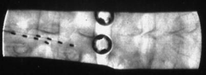

Fig. 18.11
Unilateral left leg/foot stimulation with two quadrapolar, selective, cephalocaudal electrodes. Distal electrode terminates at the L4 foramen stimulating the L4–S1 roots with an anode at the foramen, and three proximal cathodes. The proximal electrode stimulates the L3 and L4 roots programmed the same way. As pulse width is increased, geographic paresthesia coverage is increased in the left L3–S1 dermatomes
To stimulate the pelvic roots, a quadrapolar electrode enters the midline at L2–3 and remains there until it crosses S1 before it is rotated to, but not through, the ipsilateral S2 foramen. A second electrode is positioned in the same fashion contralaterally for bilateral pathology (Figs. 18.1, 18.2, 18.3, 18.4, 18.5, 18.6, 18.7, 18.8, 18.9, and 18.10). These electrodes are also programmed with a distal anode at the foramen, and up to three cathodes over the proximal S2–4 roots, respectively. This allows an anatomical placement for stimulating all of the following conditions: urge incontinence, neurogenic bowel dysfunction, urgency-frequency syndromes (including detrusor dysfunction), pudendal neuralgia, vulvadynia, and interstitial cystitis [15, 16]. This may be done as well with small paddle style electrodes through a small S1 laminotomy (Fig. 18.12). To ease placement of the paddle toward the S2 foramen, a Penfield 3 can be used at the laminotomy to elevate the electrode into position (Fig. 18.13). Given the relative lack of cerebrospinal fluid at the S2 level, most patients feel initial paresthesia at low thresholds (0.7–1.2 V) with maximal tolerable intensity approximately 1.5 times that level (1.2–1.7 V).
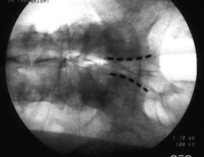

Fig. 18.12


Bilateral pelvic stimulation with 3.8-mm quadrapolar, selective, cephalocaudal paddles (S1 laminotomy). Distal contacts are anodes at each S2 foramen, and proximal three contacts are each cathodes
Stay updated, free articles. Join our Telegram channel

Full access? Get Clinical Tree


