Figure 6.1 Anatomy of the lung. While lung ultrasonography actually does not rely on specific anatomic structures within the lung, it is important to recognize the relationship of the lung with other structures in the thoracic cavity. Artwork created by Emily Evans © Cambridge University Press.
Technique
Point-of-care questions
Transducer selection and orientation
Virtually all types of transducers (Figure 6.2a) have been successfully used in pulmonary ultrasound. The most frequently utilized transducers are the convex 2–5 MHz and linear 5–10 MHz transducers. Convex-array (or abdominal) transducers can also be used, but calcified ribs can be somewhat of an obstacle because of the large footprint. As a general rule, a small-footprint transducer should be used in order to allow for imaging between the ribs. However, the footprint should not be so small that the ribs are not visualized on a longitudinal intercostal scan, since they are the reference to identify the pleural line and lung sliding. This is not a major concern when imaging younger children with non-calcified ribs, where one can image through them and still have their visual reference (Figure 6.5d). Usually a microconvex transducer (Figure 6.2b) offers a small footprint that still allows for visualizing ribs, while maintaining a good image resolution. This transducer can also image other structures like the heart and abdomen, allowing for the quick, complete examination of an unstable patient without changing transducers. If a microconvex transducer is not available, a phased-array transducer offers the same flexibility, but with worse image resolution in the proximal fields. Overall, linear transducers offer the best resolution. Their depth is much more limited, to usually not more than 8 cm. However, this does not seem to be a hindrance in the pediatric population, if the examination is going to be limited to the pleural level. Most of the pediatric literature has described lung ultrasounography with linear transducers.
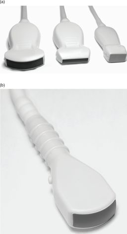
Figure 6.2 Transducers. The most commonly used transducers for lung ultrasonography: (a) curvilinear (left), linear (center), and phased array (right). (b) Microconvex transducer.
Paradoxically, modern and advanced ultrasound machines can pose a problem for optimal lung imaging, since these devices excel in eliminating artifacts, which are actually what is needed to image the lung. Usually if a modern machine offers a preset for lung, it will most likely be optimized for pleural effusion, but not for the air artifacts. Older devices with minimal post-processing capabilities tend to generate excellent lung imaging. We encourage the reader to take a look at an older machine prior to programming a lung preset on a modern device. A cardiac preset is usually a good starting point. Make sure to turn off all the post-processing filters, adjust the setting “persistence” to zero, and pick a high-contrast grayscale map.
Patient position and preparation
The pulmonary surface is quite large, and a complete examination would require quite a long time. In most cases, a very focused examination will be much more rapid, and will provide the diagnostic answer to the condition we are looking for. Usually a two-phase approach is recommended: initially performing a quick screening scan in the resuscitation phase, followed by a more comprehensive examination. The patient can be examined in a supine or seated position, obviously depending on the clinical condition. In general, pleural effusions are more easily detected in a seated patient, while pneumothoraces are more easily detected in a supine patient. The lateral decubitus positioning can be used to assess the posterior regions on a ventilated patient.
Screening examination
On the initial assessment of an unstable patient, the “A” (airway) and “B” (breathing) of the resuscitation algorithm can be evaluated with examination of two single locations on each side of the chest wall (Figure 6.3). Considering that free air is less dense and fluid is denser than the pulmonary parenchyma, air will behave like a bubble and rise, and fluid will flow to the more dependent regions. The highest spot on each side of the chest, which on the supine patient is approximately at the level of the fourth intercostal space slightly medial to the midclavicular line (Figure 6.3a), will have the highest sensitivity to exclude a pneumothorax. This location can also be used for the indirect assessment of correct placement of an endotracheal tube. A posterolateral scan, in a supine patient (Figure 6.3b), will have high sensitivity for excluding a hemothorax or pleural effusion, particularly at the level of the costophrenic recess. This posterolateral scan is similar to the transducer placement used for the FAST examination, which is a natural transition from the pulmonary examination.

Figure 6.3 Screening examination. (a) Limited lung examination, which is useful post-intubation and for screening for a pneumothorax. The highest spot on the chest is the first scanned. This is usually at the midclavicular line, at the level of the fourth intercostal space. (b) Limited lung examination to identify a hemothorax/pleural effusion. The second scan is at the most posterior spot that can be reached without rotating the patient.
Comprehensive examination
Many techniques have been developed in order to simplify the examination of the entire lung surface, particularly for interstitial syndromes. The method currently recommended by a consensus of experts consists of performing “one spot” scans of 11 regions of the thorax, 6 at each side, with exclusion of the cardiac region on the left (Figure 6.4). With this approach, a very large area of the pulmonary surface is covered within a very short time, while obtaining a good evaluation of the extent of pathology. The regions on each side are the superior and inferior halves of the anterior aspect of the chest, vertically limited by the parasternal, midclavicular, and anterior axillary lines, and superior and inferior halves of the lateral wall between the anterior and posterior axillary lines. The cardiac region (lower medial on left anterior chest) is excluded.
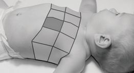
Figure 6.4 Comprehensive examination. The 11 regions of the comprehensive examination. This includes superior and inferior regions of each side, limited by the parasternal, hemiclavicular, anterior axillary, and posterior axillary line. The cardiac region is excluded (shaded).
Detailed examination
If we continue to suspect the presence of a small pulmonary consolidation and effusion, a “whole lung” examination can be performed by scanning all intercostal spaces in their entire extent anteriorly, laterally, and posteriorly, from cranial to caudal. In adults and teenagers, this can be more laborious, but in smaller children a large-footprint transducer and the absence of calcified ribs renders this examination quite straightforward. In addition, when we already know there is a focal pathologic process previously found during our screening or comprehensive examinations or by other methods (chest radiograph, CT scans), we can directly examine the region we already know contains the disease.
Ultrasound imaging: artifacts and signs
The normal lung
It is of utmost importance to master the correct identification of the pleural line within the chest wall, while avoiding its confusion with muscle and fascia layers. The pleural line can be identified as a hyperechoic line immediately deep to the ribs. The ribs are the visual reference points to finding the pleural line (Figure 6.5a). Start by imaging the lung at the level of an intercostal space with a longitudinal transducer orientation, with the indicator towards the patient’s head. The first step is to identify the ribs with their posterior shadows. These shadows follow the transducer’s array: with linear transducers they are vertical and parallel to each other and with phased-array or convex-array transducers they are divergent. The pleural line is then identified immediately below the ribs and should exhibit lung sliding. The typical image formed by two ribs with the pleural line between them is referred to as the “bat sign,” resembling a bat with open wings (Figure 6.5b,c). The normal artifact pattern is present underlying the pleural line, where “A-lines” can usually be identified. In many cases, the simple identification of the presence or absence of lung sliding is enough to obtain a diagnosis, but if more detailed pleural visualization is necessary, the transducer can now be rotated 90° to a position parallel to the length of the intercostal space, removing the ribs from the field and increasing the surface of visualized pleura.
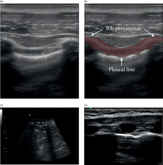
Figure 6.5 Lung imaging, the pleural line. (a) Lung sliding is present at the level of the pleural line (arrowheads), immediately deep to the ribs (R). (b) The landmarks for identifying the pleural line are referred to as the “bat sign,” where the wings of the bat represent the ribs and the pleural line is the bat’s body. Illustration by Laura Berg, MD. (c) The “bat sign” with the curved-array transducer. (d) The pleural line and ribs in a baby; the ribs are non-calcified and the entire pleural line is visible deep to the ribs.
Lung sliding
This is the starting point for all lung ultrasound, and is the basis to understanding all other pleuropulmonary pathology. Acquiring the ability to adequately identify the presence of the “lung sliding” will allow the examiner to identify the normal lung. Alternatively, the absence of “lung sliding” may be evident with a pneumothorax, and is an indirect sign of improper endotracheal intubation.
The anatomic plane where the visceral pleura glides on the parietal pleura appears as a nearly straight hyperechoic line along the chest wall on sonographic imaging (Figures 6.6a, 6.7a). During normal ventilatory movement, this line exhibits a to-and-fro movement synchronized with the respiratory cycle. This line has a slightly rough sonographic texture that is caused by the reflection of the ultrasound on the alveolar surface within the pulmonary parenchyma. This is where the reflection occurs, and this texture is what allows us to perceive movement on this line. This moving image is called “lung sliding,” and its detection conveys the fact that the visceral pleura is in direct contact with the parietal pleura and that there is lung expansion. The lung sliding is less prominent at the apical regions, where there is less pulmonary expansion, and more prominent on the bases, where there is maximal expansion and pleural gliding. At the costophrenic sinuses the “curtain sign” can be seen, when the aerated lung slides into the image during inspiration, “covering” the image of the subdiaphragmatic structures like a curtain.
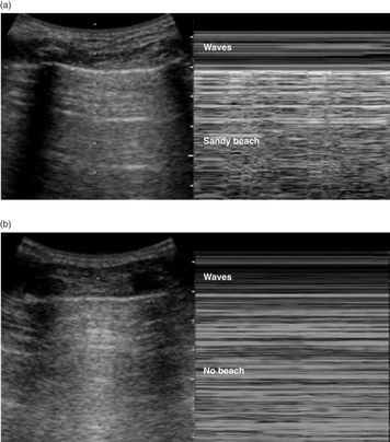
Figure 6.6 M-mode. (a) The “seashore sign” is normal lung sliding in M-mode, which generates a pattern of two different regions: waves and a sandy beach. The horizontal lines (waves) register the absence of movement of the chest wall, and the artifacts deep to the lung sliding on the pleural line generate the grainy pattern (sandy beach). (b) The “stratosphere sign” is the absence of pleural contact; all the artifact is static, as well as the chest wall, generating only horizontal lines in M-mode. This pattern is seen with a pneumothorax.
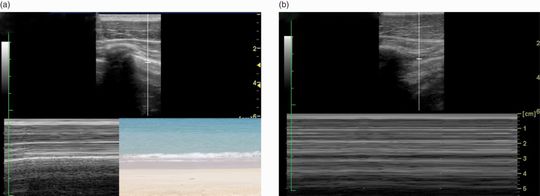
Figure 6.7 M-mode. (a) The “seashore sign” in M-mode, using a linear transducer. (b) The “stratosphere sign” in M-mode, using a linear transducer.
M-mode signs: seashore and stratosphere signs, lung pulse
On M-mode, the entire image deep to the pleural line is a reflection artifact; on dynamic imaging, it exhibits a typical “sparkling” pattern synchronized with the pleural movement. In order to capture a still image of this dynamic process and improve the visualization of lung sliding, M-mode can be utilized to generate what is known as the “seashore sign” (Figures 6.6a, 6.7a). This sign is so named because the non-moving chest wall appears as horizontal lines (ocean waves) and the sparkling artifact appears as a grainy pattern (sandy beach) (Figures 6.6a, 6.7a). It demonstrates that the visceral pleura slides directly on the parietal pleura by using one single still image. In contrast, the “stratosphere sign” is the classic sign present in pneumothorax (Figures 6.6b, 6.7b). The ultrasound beam hits the free air directly beneath the parietal pleura after traversing the chest wall, and is immediately reflected back to the transducer without any scatter caused by the underlying alveolar structure. In addition to abolishing lung sliding, the pneumothorax also disrupts the “sparkling” artifact deep to it. All the artifact deep to the pleura line will be static. Therefore M-mode will register only horizontal lines: the “stratosphere sign” (Figures 6.6b, 6.7b). The “seashore sign” and “stratosphere sign” M-mode patterns can also be seen with a linear high-frequency transducer (Figure 6.7a,b).
In the non-ventilated lung (i.e. apnea, mainstem intubation, complete atelectasis), the visceral pleura will still present with a tiny rhythmic movement synchronous with the cardiac cycle, caused by the arterial pulse, and by the movement of the heart itself. This can be perceived as minute to-and-fro movements visually identical to the lung sliding, but short and rapid. The presence of this “lung pulse” means that there is pleural contact but there is no pulmonary expansion. M-mode will register rhythmic interferences on a striped seashore pattern (Figure 6.8). This can easily be simulated in the normal individual by holding one’s breath.
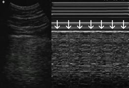
Figure 6.8 Lung pulse. In the absence of lung expansion, the systolic cardiac pulsation can be visualized as a rhythmic movement of the pleural line. This can be seen as regular perturbations in the “seashore sign” (arrows), synchronous with the heartbeat.
Water-content artifacts: A-lines and B-lines
“A-lines” (Figure 6.9a,b) are horizontal lines parallel to the pleural line, and are a product of the reverberation of the ultrasound beam between the pleura and the transducer. Since A-lines are generated by the presence of air, as in normal parenchyma, they will also be present in aerated pathologic conditions, such as a pneumothorax or a mainstem intubation. Of note, A-lines are not always seen; their expression depends on the machine’s settings and processing filters. The production of A-lines also depends on the transducer’s scanning angle; using a perpendicular scanning angle most often generates them.

Figure 6.9 A-lines. (a) A-lines (arrows) are reverberation artifacts that reproduce the image of the pleural line (arrowheads). (b) Longitudinal intercostal scan, normal lung: the ribs (R) are seen in the chest wall (CW). All of the image deep to the pleural line is artifactual (Art), composed of the rib shadows and the A-lines (arrows) within the sparkling pattern artifact.
Related posts:


Stay updated, free articles. Join our Telegram channel

Full access? Get Clinical Tree


