CHAPTER 31
Provocative Discogram
INTRODUCTION
Discography has been practiced by interventional pain physicians for the last few decades in an attempt to identify the pain generator in the lumbar or the cervical spine (and less commonly the thoracic spine). Although this procedure was initially intended to identify a pain generator that can be surgically treated with a fusion, it was eventually utilized to diagnose a contained disc herniation as well as internal disc disruption. Evolution of intradiscal procedures such as IntraDiscal Electrothermal Treatment (IDET), percutaneous disc decompression, cooled radiofrequency use for biacuplasty, etc, have led pain physicians to perform these procedures as minimally invasive treatment options for disc pathology.
In a lumbar disc, the intradiscal pressure increases based on the spine position. While the pressure is at the baseline while lying down, it does increase somewhat when standing. However, sitting can increase the pressure to almost twice as much, as the lumbar spine flexes and the relaxed muscles do not contribute as much in weight bearing. Bending forward while sitting can increase the pressure to almost 3 times and adding a twisting movement can increase it to 4 times as much as standing. A patient complaining of pain in the lower back while performing any of these activities, and does not have any obvious cause for the back pain is a good candidate for this procedure.
Indications
• Provocation discography is performed to identify a disc that is likely source of pain.
• Other diagnostic tests have failed to clearly confirm a suspected disc as a source of persistent pain.
• Assessment of discs prior proposed fusion of segment with symptomatic discs, and whether the discs adjacent to this segment can support a fusion.
• Assessment of candidates for minimally invasive surgery who have confirmed disc herniation.
• Evaluation of abnormal discs or recurrent pain from a previously operated disc.
• Assessment of patients in whom surgery has failed, to determine whether pseudoarthrosis or a symptomatic disc to be the source of pain.
DIAGNOSTIC PROVOCATIVE DISCOGRAPHY
Purpose
The purpose is to simulate disc loading in a lumbar disc that happens with forward flexion and increased intradiscal pressure. This may be reported by a patient as sitting intolerance, aggravation of back pain while bending forward, etc. Provocative discography is the procedure performed to reproduce discogenic pain by injecting contrast in the disc. The pain is reproduced either by chemical irritation of sensitive tissue, or by increasing the intradiscal pressure due to volume and stretching the annular fibers of the disc. Discography helps to evaluate disc morphology and confirms the diagnosis for consideration of surgical intervention. It also helps to identify the normal discs.
• Diagnostic purpose to identify the pain generator for back pain which is mechanical and axial in origin and neck pain which is axial and no other pain generator can be identified.
• Identify the painful disc as a preoperative diagnostic indicator to facilitate a surgical intervention.
• Identify a contained herniation, internal disc disruption, or a leaking disc (common cause for painful inflammatory radiculitis).
RELEVANT ANATOMY OF THE DISC (FIGURE 31-1)
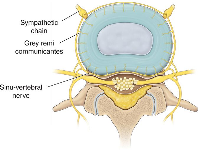
Figure 31-1. Disc anatomy. S.C., sympathetic chain; G.R., grey remi communicantes; SV.N, sinuvertebral nerve.
The lumbar or thoracic intervertebral disc can be approached through a posterolateral approach in a prone patient, while the cervical disc can be approached through an anterolateral approach.
• Outer annulus (annulus fibrosus)—tough fibrous multilayered but flexible structure. Made up of 15 to 25 concentric layers called lamellae
• Inner nucleus (nucleus pulposus)—softer inner core of the disc containing proteoglycans
• Bound above and below by the cartilaginous end plates
Innervation
• Recurrent sinuvertebral nerve (ascending and descending branches)—branch of the grey rami communicantes.
• The posterior longitudinal ligament (PLL) is richly innervated by the ascending sinuvertebral nerve.
Blood Supply
• Segmental arteries located at the waist of the vertebral body and supplying the end plates through ascending and descending branches.
• A normal disc is essentially avascular and aneural.
• A pathological disc develops neo-vascularization and proliferation of nociceptive nerve endings.
ANATOMY OF CERVICAL DISCS
Cervical discs have certain characteristics distinct from other parts of the spine.
• The posterior longitudinal ligament in the cervical region is thicker, with a double layer, enclosing the posterior and lateral parts of the disc, while it is a much thinner, single layer, with a weaker lateral protection in the lumbar area.
• The nuclear material of the cervical disc lies more anterior than it does in the lumbar spine; therefore, posterior displacement difficult to occur unless great forces are applied on the disc.
• The outer annulus is substantially thicker in the posterior portion of the cervical disc, making it more difficult for the disc to bulge posteriorly.
• The anterior aspect of the disc receives sensory innervation from the sympathetic chain and the posterior aspect receives innervation from the sinovertebral nerves. It is thought that these nerves provide innervation to the facet joints as well.
ANATOMY OF THORACIC DISCS
• Thoracic discs are located between the cartilaginous end plates of the vertebrae above and below it.
• The disc of the thoracic spine is characterized by a thick fibroelastic annulus that surrounds a gelatinous nucleus pulposus.
• These annular fibers run in an oblique direction from adjacent vertebrae.
• These annular fibers receive sensory input from various sources including sinovertebral nerves (posteriorly) and the sympathetic chain (anteriorly).
ANATOMY OF LUMBAR DISCS
• Radicular pain of discogenic origin is much more common in the lumbar region than any other region.
• Unlike the cervical region, the bony facets do not protect the nerve roots.
• The posterior longitudinal ligament of the lumbar spine is thinner and less protective. This is especially true in the lateral aspects of the spine.
• The nuclear material in the lumbar spine is located more posterior than that of the cervical or thoracic spine.
• The innervation of the lumbar discs is very similar to that of the discs of the cervical and thoracic spine. The outer third of the annulus fibrosus of the disc is supplied by multiple sensory nerves.
BASIC CONCERNS AND CONTRAINDICATIONS
• The risk and benefit ratio for a diagnostic discogram has to be considered and should be performed only after all the other diagnostic and therapeutic options have been exhausted.
• Discitis remains the single most dreaded complication from this procedure and all precautions need to be taken to avoid it.
• Lack of good blood supply to the disc makes the treatment of discitis very difficult with a prolonged morbidity.
• Any local and systematic infection is a contraindication for these procedures.
• Patient is unable to understand the procedure and unwilling to provide the written consent.
• Proper training and experience are a must.
PREOPERATIVE CONSIDERATIONS
• Proper education of the patient is required especially as the main purpose is mostly diagnostic.
• Anticoagulant status—stop before the procedure at appropriate time depending on the anticoagulant.
• Confirm the painful side—approach from the other side so that the pain is not reproduced just by accessing the damaged side of the disc.
• Intravenous access for antibiotic prophylaxis only. Sedation is best avoided for proper diagnostic value of the procedure.
Fluoroscopic views (Figures 31-2 and 31-3A, B)
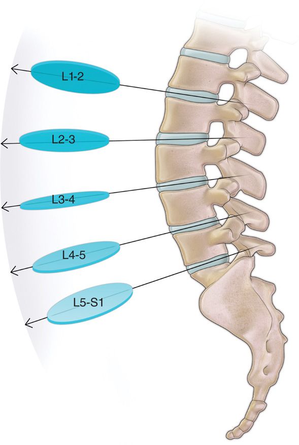
Figure 31-2. Fluoroscopic angles for various lumbar discs.
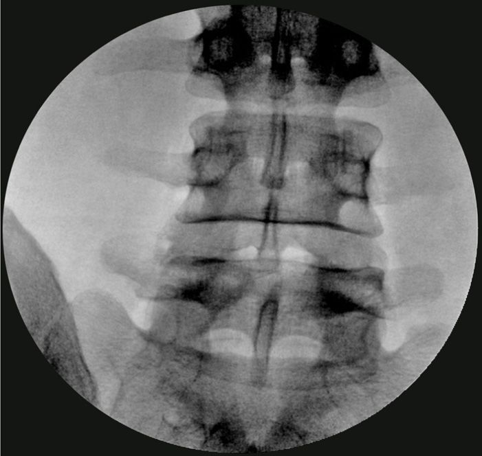
Figure 31-3. (A, B) “Squared” lumbar disc and entry point anterior to the lower superior articular process (SAP).
• AP fluoroscopic view to identify the level of the lumbar discs.
• View is then angled cephalad-caudad to “square” off the intended disc endplates.
• Oblique view toward the side of entry (ipsilateral oblique view) so that the articular elements bisect the superior end plate.
• Entry point is just lateral to the superior articular process (SAP) of the inferior vertebral body.
• Multiple AP and lateral views may be needed to properly place the needle tip within the center of the nucleus pulposus.
Equipment
• A sterile environment with proper imaging capability is very important.
• Choice of needles depends on one’s training and experience. A single needle versus a dual needle technique has been used.
• Although there is not much data to suggest any higher rate of infection with a single needle technique, proponents of the dual needle technique tout the safety of using a needle through a needle and thus minimizing the chances of possible infection.
• A dual needle technique also allows for a smaller needle to be used to access the nucleus and thus reducing the size of the needle puncture in the annulus.
• Manometric measurements provide added information, thus improving the utility of this procedure.
• A single unit made up of a controlled injection syringe and a built in digital pressure monitor is the latest device available. However, a controlled injection syringe connected to a separate pressure monitor is also used. The data is presented in various formats (Figures 31-4 and 31-5).
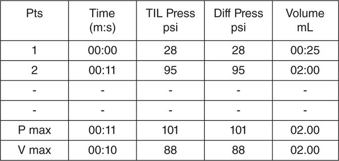
Figure 31-4. Numeric pressure reading printout (lumbar disc).
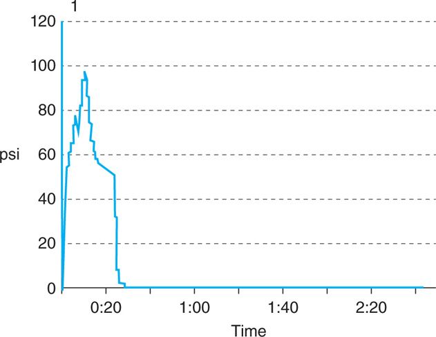
Figure 31-5. Graphic pressure recording (lumbar disc).
• Injectate is typically made up of the radio-opaque water soluble contrast media with mixed in antibiotic.
Technique
The approach to the intervertebral disc is typically through the posterolateral angle in the lumbar and thoracic discs and through the antero-lateral angle in a cervical disc.
Lumbar Discogram
• Prophylactic antibiotics should be considered as per protocol.
• Patient is placed prone with a pillow under the abdomen to reduce the lumbar lordosis.
• Fluoroscopic view is optimized so that the intended disc is “squared” (the x-ray beam passing perpendicular to the disc so that there is no parallax and the end plates are seen as a single thick line.
• The obliquity of the view is advanced up to a point where the articular elements of the lower vertebral body bisects the upper end plate in oblique fluoroscopic view.
• The entry point is then marked just anterior to the superior articular process of the inferior vertebral body under fluoroscopic guidance.
• A 22-gauge 13-cm styletted needle is placed through the skin and advanced to the middle of the disc of question.
• The needle is advanced incrementally under fluoroscopic guidance in AP, lateral, or oblique views as needed. If a paresthesia is elicited, the needle should be withdrawn and then redirected cephalad toward the middle of the disc.
• Once the disc is contacted, the needle is advanced incrementally until the middle of the disc is penetrated. Imaging is performed in order to avoid penetration though the back of the disc or too laterally either into the spinal canal or the pleura (in L1 discography).
• The syringe filled with preservative-free contrast is then connected to disc pressure monitor, and attached to the needle and zeroed. Gradual injection of the injectate is done using live fluoroscopic view.
• 0.5 to 2.0 mL of preservative-free contrast suitable for intrathecal use is injected with careful attention being paid to initial pressure to injection via manometry, patient’s response, and whether or not the pressure is maintained or dissipated in the disc.
• Take note of volume of contrast injected, volume at which patient experienced pain, pressure at which patient experienced pressure and/or pain, and pain response in terms of its location, character, distribution, intensity, and concordance with chronic pain.
• The discogram should be evaluated to check the integrity of the disc and a decision should be made if there is a need to evaluate the adjacent disc spaces, or to inject local anesthetic in the disc of question.
• The injection of local anesthetic into this disc space may give erroneous information if the adjacent discs are to be evaluated. The local anesthetic can possibly track epidurally or it can anesthetize some of the nerves that provide sensory input to the adjacent discs.
Cervical Discogram
Prophylactic antibiotic should be considered. The patient is placed in supine position with a pillow under the shoulders and the neck extended.
• Fluoroscopic view is directed in an oblique manner with a caudad-cephalad tilt to “square” the targeted disc.
• The obliquity is advanced to optimize the view of the foramen at the given level on the right side.
• Right side is most commonly chosen to avoid accidental puncture of the esophagus which needs to be further pushed away with the nondominant hand.
• Important structures must be noted at this level including the trachea, carotid artery, jugular vein, and esophagus.
• The medial border of the sternocleidomastoid muscle is palpated and local anesthetic is injected subcutaneously at the chosen level of cervical disc.
• A short 22- or 25-gauge styletted needle is inserted under live fluoroscopy within the nucleus.
• A small amount (usually 0.3 to maximum of 0.4 mL) of contrast is injected while paying attention to resistance to injection and patient’s response to provocation of pain.
• Make precise notes of volume of contrast injected, volume at which patient experienced pain, pressure at which patient experienced pressure and/or pain, and pain response (location, character, distribution, intensity, and concordance with chronic pain).
Thoracic Discography
• Prophylactic antibiotics should be considered as per the protocol.
• Patient is placed in prone position with a pillow under the lower chest in order to flex the spine.
• If CT scan is being used, make careful note of pleura, lung, ribs, nerve roots, and spinal cord.
• The area over the discs of question marked under fluoroscope wide are laterally on either side is prepped, draped, and anesthetized.
• A 22- or 25-gauge styletted needle is placed through the skin and advanced to the middle of the disc of question under fluoroscopic guidance.
• The needle is advanced incrementally with imaging. If a paresthesia is elicited, the needle should be withdrawn and then readvanced toward the middle of the disc.
• Once the disc is contacted, the needle is advanced incrementally until the middle of the disc is penetrated. Imaging is performed in order to avoid penetration of the back of the disc either into the spinal canal or the pleura.
• Similar to the cervical discogram, 0.3 to 0.4 mL of preservative-free contrast approved for intrathecal use is injected with careful attention being paid to resistance to injection, patient’s response, and whether or not a pressure is maintained or dissipated in the disc via manometry.
NORMAL AND ABNORMAL FINDINGS (FIGURES 31-6A–C, 31-7, AND 31-8)
• The images of the injected disc should be evaluated to see whether or not the disc and its components are intact.
• The morphology of the disc will determine where the contrast will flow.
• A normal disc will appear as a lobulated mass with some posterolateral clefts and high pressure on manometry.
• If the inner annulus is torn, a transverse pattern of contrast will show on the nucleogram or if the tears of the annulus extend to the outer layer, a radial pattern will be noted.
• The contrast will flow into the epidural space, neuroforamen or the end plate of the vertebra if the annulus is completely disrupted.
• Abnormal discogram shows various contrast patterns that differ from normal silhouette of the nucleus, and may leak into annular layers or outside the annulus.
• A low-pressure abnormal disc may not be the painful when subjected to pressurization.
• Various angles of a fluoroscope may show contrast spread that could be abnormal (Figure 31-6B).
• A postdiscogram CT scan will confirm the details of disc morphology including contained herniation (Figure 31-9).

Figure 31-6. Normal and abnormal discogram levels. (A) Shows a normal silhouette of the nucleus denoting a normal disc. (B) Shows the L4-5 disc (below the needle) from a lateral aspect with some leakage into the epidural space going cephalad. (C) Shows an almost ideal discography with the degenerated disc in the middle of 2 normal discs.
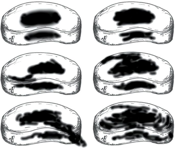
Figure 31-7. Various discogram contrast spread patterns. This figure shows various possible contrast spread patterns from a discogram. Figures 1 and 2 show a normal disc with a globular and bilobular pattern which is contained within the nucleus. Figure 3 shows an annular tear extending into the outer third posterolaterally. It is contained within the disc. Figure 4 shows a leaking disc. Figure 6 shows a severely degenerated and internally disrupted disc with annular spread but still contained.
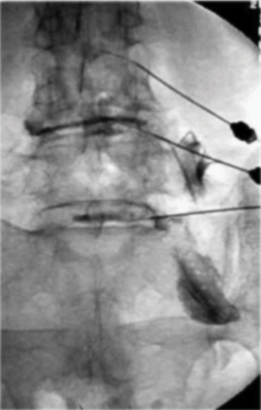
Figure 31-8. A leaking disc on discogram outlining the nerve roots. This figure shows the contrast leaking outside the degenerated disc and spreading along the nerve roots. Note the various angles of the needles for different levels of the lumbar spine.
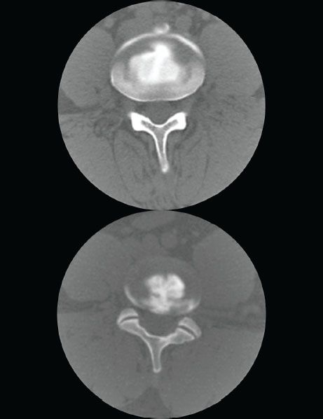
Figure 31-9. A postdiscogram CT scan. Figure shows two different discs on CT scan. The upper image shows a normal spread within the nucleus, some white areas are the bone which has the same characteristics as the contrast. The lower image shows the contrast extruding in to the annulus as a clear connection is seen between the contrast in the nucleus and the annulus.
OUR PREFERRED TECHNIQUE
Prep. Duraprep, Ioban adhesive drape, full body sterile drape, full scrub, gown, and gloves
Needles. Dual needle set (20 gauge 3.5 in + 25 gauge 5 in or 20 gauge 6 in, 25 gauge 8 in) (Figures 31-10 and 31-11)

Figure 31-10. Dual needle set for discography. Yellow hub, introducer; blue hub, discography needle.

Figure 31-11. Dual needle set (curved inner discography needle).
Manometry. Syringe and Stryker Disc monitor (Figure 31-12)

Figure 31-12. Disc pressure monitor. (Reproduced with permission from Stryker.)
Injectate. Omnipaque 180 or Isovue 200 M with cefazolin 5 mg/mL
Mixing technique. Mix 1 GM cefazolin diluted with 10 mL PFNS (100 mg/mL). Take 1 mL of this mixture and dilute it with 19 mL of preservative free contrast (100 mg in 20 mL = 5 mg/mL). Use the other 9 mL for IV injection.
Outer or introducer needle inserted using a tunnel view and advanced to within 1 mm of the annulus. The inner curved needle is then introduced through the introducer and advanced toward the middle of the nucleus using AP and lateral views repeatedly to ensure central placement (Figure 31-13A, B).
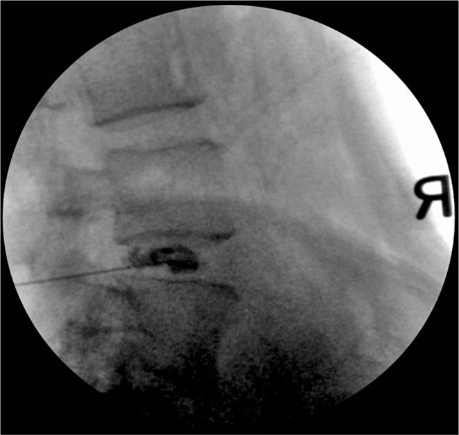
Figure 31-13. (A, B) Advantage of a curved needle (dual needle set). Even if the introducer needle is not exactly in the middle of the disc, a curved inner needle can be guided to the center of the nucleus. (Reproduced with permission from Stryker.)
The controlled injection syringe is connected to disc pressure monitor, and then attached to the needle and zeroed. Gradual injection of the injectate is done using live fluoroscopic view.
Appearance of the contrast within the disc marks the “opening pressure.” Injection gradually performed with the following end points (whichever is first).
1. Pain, whether concordant or discordant
2. Pressure up to a maximum of 120 psi (lumbar disc)
3. Volume of injectate up to a maximum of 2.5 mL (lumbar disc), 0.4 mL maximum (cervical disc)
Multiple views are obtained with the fluoroscopic guidance in AP, lateral, and axial views as much as possible using a cephalad to caudad tilt. Patient is then sent for a postdiscogram CT scan.
POSTPROCEDURE FOLLOW-UP
• Patient should obtain a postdiscogram CT scan within 30 minutes of having the procedure.
• Patient is instructed to report any fever, increased back pain, or new symptoms.
• Follow up within 1 week.
POTENTIAL COMPLICATIONS AND PITFALLS
• Injury to the tissues:
![]() Nerve root (needle too lateral or too cephalad)
Nerve root (needle too lateral or too cephalad)
![]() Blood vessels within the neural foramen
Blood vessels within the neural foramen
![]() Disc injury resulting from multiple attempts
Disc injury resulting from multiple attempts
![]() Disc infection—discitis
Disc infection—discitis
![]() Cervical level—injury to the esophagus and subsequent infection of the disc
Cervical level—injury to the esophagus and subsequent infection of the disc
![]() Cervical level—injury to the great vessels
Cervical level—injury to the great vessels
• Difficulty in needle placement—especially at the L-S1 level:
![]() Proper cephalad to caudad angle to optimize the L5-S1 disc
Proper cephalad to caudad angle to optimize the L5-S1 disc
![]() Use of a curved needle may be helpful (especially using a 2-needle technique)
Use of a curved needle may be helpful (especially using a 2-needle technique)
Stay updated, free articles. Join our Telegram channel

Full access? Get Clinical Tree


