Principles of Sonography
Paul E. Bigeleisen
Daniela Smith
Steven L. Orebaugh
The frequency of medical ultrasound ranges between 2 and 20 MHz. The speed of sound in tissues is about 1,500 m/sec. The average wavelength of the ultrasound beam in this band is less than 1 mm. This limits the use of ultrasound to structures that are 1 mm in diameter or larger (Fig. 6.1). Most nerves of interest range from 2 to 10 mm. Veins and arteries of interest are typically 3 to 15 mm.
Many factors contribute to the quality and resolution of the ultrasound image. In general, higher frequency probes generate higher resolution images. Unfortunately, the signal strength or intensity (I) of high-frequency ultrasound waves (10 to 20 MHz) is rapidly attenuated in tissue. Thus, high-frequency probes are best suited for structures less than 4 cm deep from the skin. For deeper structures, probes in the 2 to 5 MHz range are more useful (Fig. 6.2). The speed of sound in air and tissues varies from 300 m/sec in air to 4,000 m/sec in bone. In soft tissues, blood, and cystic fluid, the speed of sound is about 1,500 m/sec. Most ultrasound platforms assume an average speed for beam propagation of about 1,500 m/sec. Because the speed of sound differs slightly in different types of soft tissues, small imaging artifacts may occur as the beam passes from one tissue type to another. This occurs most frequently when the beam passes from soft tissue through blood or cystic fluid.
The ultrasound beam may be refracted as it passes through tissue. When this occurs, a nerve or other organ may appear at a different anatomical location than its actual site. This is the same phenomenon responsible for the apparent bending of your forearm when you place it in a bucket of water (Fig. 6.3). Notice that the needle appears to be bent as it enters a fluid-filled cyst in Figure 6.3B. Fat globules below the skin, in the muscle, and around nerves are about 1 mm in diameter. These globules (Fig. 6.4A) serve as scattering and diffraction sites for the incident and reflected ultrasound beam and cause a speckled appearance in the image (Fig. 6.4B, C). This is called speclation. For these reasons, obese patients can be very difficult to image (Fig. 6.5A, B).
The image formed of a nerve on ultrasound is very sensitive to the angle of incidence of the beam relative to the nerve. This is referred to as the angle of insonation. Sometimes, changing the angle of insonation by only a few degrees can bring the nerve into focus. Diffraction and scattering, as well as the heterogeneous three-dimensional structure of the nerves and their surrounding tissues, are thought to cause this phenomenon. An analogy is shown in Figure 6.6A. Here, light is shown on a three-dimensional icon. Varying the direction of the incident light beam by only a few degrees will result in a radically different shadow in any direction. To obtain the optimal ultrasound image, the image should be centered on the screen by sliding or rotating the probe on the patient’s skin. For deep structures, compressing the tissue may improve the image. Once these maneuvers have been completed, toggling will produce the best image (Fig. 6.6-Gi). Notice how the nerve disappears in the ultrasound image of Figure 6.6G(ii) with additional toggling.
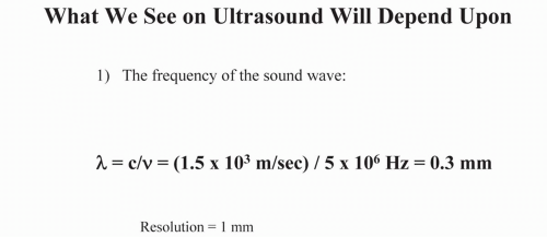 Figure 6.1. Relationship between wavelength and resolution. |
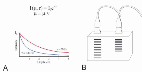 Figure 6.2. A: Equation for beam attenuation as a function of frequency. r, tissue depth; v, frequency; µ, amplitude attenuation consTant. B: Beam attenuation as a function of frequency. |
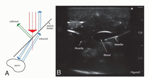 Figure 6.3. A,B: Reflection and refraction of ultrasound beam. |
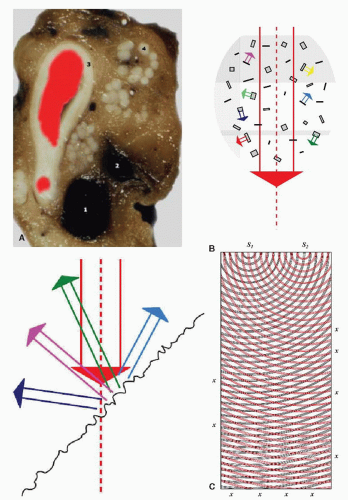 Figure 6.4. A: Cross section through the axilla. 1, axillary vein; 2, basilic vein; 3, wall of axillary artery; 4, nerve fascicles. B: Scattering from an irregular surface. C: Diffraction of ultrasound beam causing speclation. |
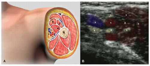 Figure 6.5. A, B: Schematic through the axilla. 1, axillary artery; 2, axillary vein; 3, biceps muscle; 4, coracobrachialis muscle; 5, branch of musculocuTaneous nerve; 6, humerus; 7, median nerve; 8, ulnar nerve; 9, radial nerve. |
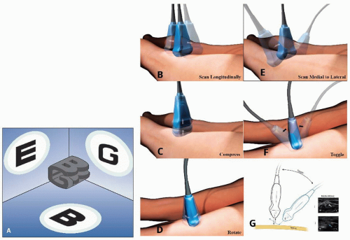 Figure 6.6. A: Relationship between beam direction and image. B-G: Different probe movements. Notice how the nerve in figure 6Gi disappears with toggling in figure 6Gii. |
Modern platforms allow the user to adjust the brightness (gain) of the entire image or more superficial (near field) and deep (far field) structures. Increasing the gain makes the entire image whiter. Increasing the gain too much creates a snowy background in which all of the structures become indistinguishable. In general, the gain should be set so that most of the background is black and only the structures of interest, such as nerves and vessels, are easily seen. Many machines have an autogain button that adjusts the gain for the user.
Modern machines also allow the user to adjust the contrast. The formal term for contrast is dynamic range compression. Increasing the dynamic range compression makes the white images whiter and the black images blacker (Fig. 6.7A). This may bring the edges of an anatomic structure into better view. Decreasing the dynamic range compression makes everything in the image a more homogeneous grey.
All machines allow the user to adjust the depth to which the probe penetrates. Whenever possible, the depth should be set to the shallowest setting in which the structures of interest are all imaged. Some machines come with a preset focal zone, and some machines allow the user to set multiple focal zones. In general, the focal zone should encompass the area of greatest interest in the image. The near focal zone has the greatest resolution and is referred to as the Fresnel zone. The deeper focal zone (far field) is referred to as the Fraunhofer zone. This zone has poorer resolution (Fig. 6.8A). Most machines allow
the user to adjust the depth of the focal zone or to set multiple focal zones (Fig. 6.8B) by adjusting the time delays between transducer elements in the probe.
the user to adjust the depth of the focal zone or to set multiple focal zones (Fig. 6.8B) by adjusting the time delays between transducer elements in the probe.
Related posts:
 Microanatomy of the Peripheral Nervous System and Stimulation Thresholds Inside and Outside the Epineurium
 Use of Ultrasound for Placement of Peripheral Nerve Block Catheters
 Ultrasound-Guided Lumbar Plexus Block (Transverse Approach)
 Ultrasound-Guided Anterior Sciatic Nerve Block
 Ultrasound-Guided Caudal, Lumbar, and Epidural Injection
 Ultrasound-Guided Genitofemoral Nerve Block
Stay updated, free articles. Join our Telegram channel

Full access? Get Clinical Tree


