PLAIN FILMS: BASICS
INTRODUCTION
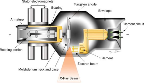
X-rays are high-energy electromagnetic waves that have been used in diagnostic imaging since their discovery in 1896 by Wilhelm Conrad Roentgen. They consist of electromagnetic components oscillating in orthogonal planes. For routine clinical use, a finely controlled x-ray beam of known energy and quantity is targeted toward the site of interest.1 An x-ray tube in its most elementary form consists of a tube filament and target (Figure 1–1). The tube filament (cathode) emits electrons when heated. A target (anode) emits x-rays when struck by these high-energy electrons. In diagnostic radiology, these x-rays pass through a patient and are attenuated to various degrees based on the density of the tissue. They then strike an image detector, leading to formation of an image. On the processed image the “lighter” areas are the attenuated x-rays, with “darker” areas of the film corresponding to areas of less attenuation. Bone, the densest tissue, appears bright white on plain film, while soft tissue is of intermediate attenuation, and air appears black (Table 1–1).
Figure 1–1 Schematic illustration of an x-ray tube.
The aim of the sections that follow are twofold:
I. To provide a brief overview as to the interpretive approach to chest and abdominal x-rays
II. To describe salient findings in common clinical conditions encountered in the emergent surgical setting.
CHEST PLAIN FILMS
The chest radiograph or chest x-ray (CXR) is one of the most commonly ordered examinations in the emergency department. It provides a quick preview of the thorax with minimal cost, minimal patient discomfort, and minimal radiation risk. A single chest x-ray provides a radiation dose of approximately 0.01 to 0.02 mSv.2 This dose is equivalent to a background radiation dose for an entire day, and the clinical benefits conferred by a chest film far outweigh this negligible radiation exposure.
 Standard CXR Views3
A CXR view depends on the direction in which the rays pass from the tube through the patient.
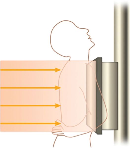
• Postero-anterior (PA) CXR: This is obtained with the patient standing and facing the film cassette with a distance of 180 cm from tube to cassette. The x-rays pass from the posterior to anterior direction. This is the standard preferred projection of a CXR and should be obtained whenever feasible. It allows accurate and valid comparison between separate previous radiographs (Figure 1–2).
Figure 1–2 Illustration showing the position for obtaining a PA CXR.
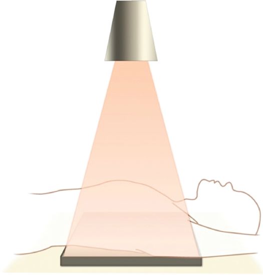
• Antero-posterior (AP) CXR: An AP CXR is obtained when the patient is unable to sit or stand. With the advent of portable x-ray machines, the AP CXR is commonplace, especially in the intensive care unit (ICU) setting. The detector is placed behind the patient in supine position, and the patient’s anterior chest wall faces the tube at a distance of approximately 100 cm. One drawback of this view is that this reduced distance can result in magnification of otherwise normal-appearing structures (Figure 1–3).
Figure 1–3 Illustration showing the position for obtaining an AP CXR.
Pitfalls:
AP films have several pitfalls and should be interpreted with caution:
 The heart and hila are magnified, leading to a false impression of cardiac enlargement.
 Comparison between AP and PA films is unreliable.
 The patient may be unable to take a full inspiration, leading to elevated diaphragms and poor visualization of lung windows.
 Small pneumothoraces and effusions may be missed as air (in anterior positions) and fluid layer (in posterior positions).
 If the anterior ends of at least 6 ribs do not lie above the left hemidiaphragm, poor inspiration should be suspected.
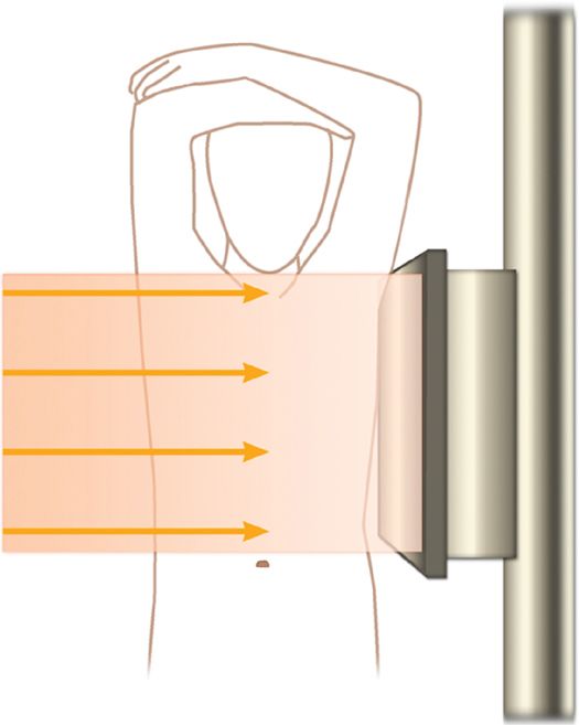
 Lateral CXR: A lateral film is usually obtained with the patient standing with arms elevated and with the right or left chest wall in contact with the cassette. This projection is acquired if the PA CXR is equivocal, to aid in localization of focal lesions (Figure 1–4).
Figure 1–4 Illustration showing the position for obtaining a lateral CXR.
 Approach to Reading a CXR
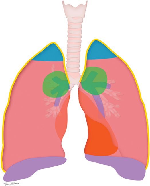
Various opinions exist on how to best read a CXR, but every CXR should be analyzed in a systematic manner to ensure that no critical findings are missed. The tendency when first viewing a chest film is to focus immediately on the lung fields. Unfortunately, this practice results in failed recognition of pathology. Figure 1–5 depicts anatomic areas frequently overlooked when interpreting a CXR.
Figure 1–5 Commonly overlooked areas on a CXR, represented by the blue, green, red, and purple areas.
To ensure no missed diagnoses, evaluate the bones, diaphragms, mediastinum, peripheral chest wall, and lung fields in a systematic fashion. The technique adopted matters less than does the regular practice of being methodical, thorough, and consistent. One popular mnemonic for CXR interpretation, the “ABCD” algorithm, appears in Table 1–2 and can aid the novice in developing a reliable routine.
Normal CXR
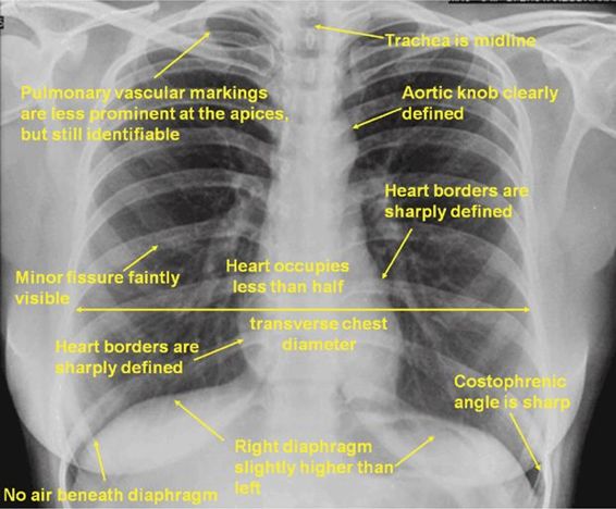
Figure 1–6 outlines features of a normal CXR. To summarize, the chest wall and diaphragms—gradations of gray and white—outline the black lung fields. The mediastium bisects the lung fields, and in a normal patient, the heart has sharp borders and occupies less than half the transverse chest diameter. The trachea is visible as a lucent stripe in the upper mediastinum and in the normal patient is midline. Pulmonary vascular markings are less prominent at the apices of the lungs than at the bases, but in the absence of pneumothorax, they are still appreciable, especially when the area of interest is magnified using a zoom function. The right diaphragm is slightly higher than the left one given the underlying liver, but in a normal patient, both costophrenic angles are sharp.
Figure 1–6 Features of a normal CXR.
Abnormal CXR
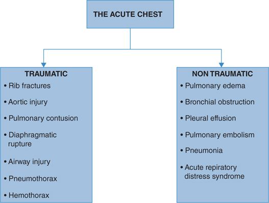
As the schematic in Figure 1–7 depicts, accurate identification of pathology on a chest film depends on each clinical scenario. The following discussion outlines methods to recognize key findings in trauma and other emergent surgical situations.
Figure 1–7 Differential diagnosis of acute pathology identifiable on CXR.
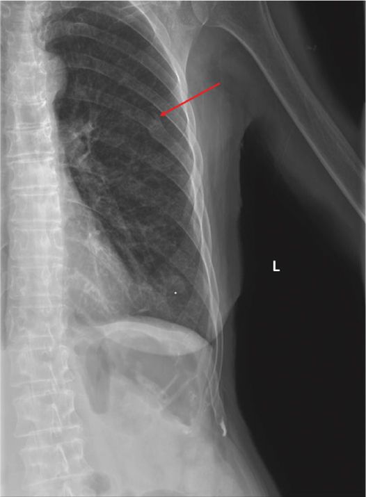
On a CXR, displaced fractures may be seen as a break in the outlines of the ribs as they are traced from posterior to anterior. The normally smooth contour of the rib appears jagged, irregular, or disrupted (Figure 1–8).
Figure 1–8 PA CXR showing fracture of posterior part of sixth rib on the left side (arrow).
Pearls:
 The term “flail segment” describes fractures of two or more ribs at two or more places or fractures of the ipsilateral clavicle and the first rib.4 It implies significant intrathoracic injury, secondary to pulmonary contusion. Patients with flail chest have deranged respiratory mechanics and usually require positive pressure ventilation.5,6
 If in doubt about whether a lesion is in lung or rib, obtain an AP film. Rib lesions will remain in the same position relative to the rib in question.
Aortic Injury
Aortic injury confers a high mortality, with only 10% of patients reaching the hospital.4 For those who do survive, a high index of suspicion is paramount to the diagnosis.
Numerous signs on x-ray have been described to detect aortic injury7,8 (Table 1–3). The presence of any of these signs should trigger further investigation by a computed tomography (CT) angiogram. As Figure 1–9 demonstrates, widening of the mediastinum on plain film in the trauma bay after high-velocity blunt trauma should raise concern for aortic injury.
Figure 1–9 Widening of superior mediastinum (arrow), suspicious for aortic injury in a patient status post motor vehicle accident.
Pearls:
 If aortic injury is clinically suspected, attempt to trace the normally sharp aortic outline. An obscure and difficult-to-trace outline increases the likelihood of an aortic injury, and often this is the only suggestive finding on plain film. Remember that the aortic root is not seen even in normal patients.
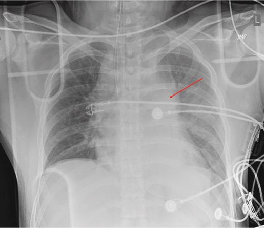
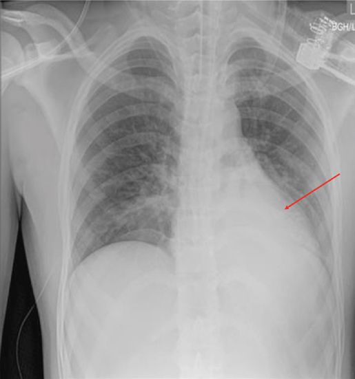
Pulmonary contusions appear on plain films as patchy consolidations, usually underlying a rib fracture. They present as hazy, lighter areas in the otherwise dark lung fields and are difficult to differentiate from aspiration or pneumonia. Acute trauma with multiple rib fractures increases the likelihood that a consolidation represents contusion, while multiple facial fractures and depressed mental status, in the absence of significant chest wall injury, raise suspicion for aspiration. In the stable patient, a chest CT can clarify the diagnosis (Figure 1–10).
Figure 1–10 CXR showing subtle increase in retrocardiac density (arrow) after blunt trauma. On CT scan, this area proved to be a pulmonary contusion.
Airway Injury
Suspect airway injury after trauma if the following are present:
• Pneumomediastinum
• Pneumothorax
• Subcutaneous emphysema in neck
• Lung/lobar collapse
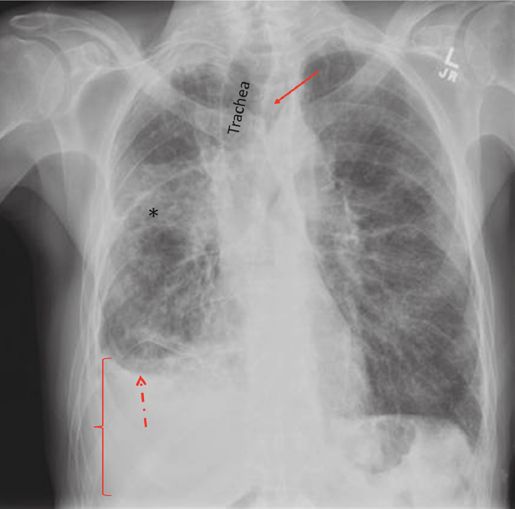
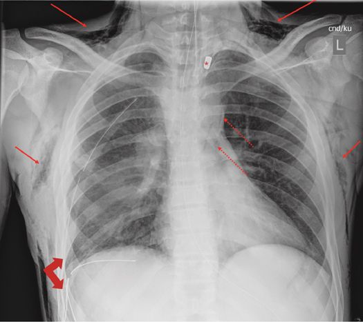
Subcutaneous emphysema appears as linear areas of lucency superimposed on the soft tissues of chest wall and neck. Clinically, the subcutaneous crepitus can be felt over these regions. Pneumomediastinum appears as areas of lucency within the mediastinum, outside the trachea. Pneumothorax is discussed below in detail (Figures 1–11 and 1–12).
Figure 1–11 CXR in a patient with airway injury. Note the pneumomediastinum (solid arrow), seen as a lucent area in the mediastinum separate from the trachea. This patient also has a right pleural effusion (bracket)—possibly hemithorax—identifiable as opacification of the right pleural base with blunting of the costophrenic angle, as well as a fluid meniscus (dashed arrow). Consolidation is also seen (asterisk), which in the setting of trauma may represent aspiration or pulmonary contusion.
Figure 1–12 Supine CXR in a case of gunshot injury. Note the extensive subcutaneous emphysema (solid arrows). Also note bullet lodged in left upper lung zone (asterisk), pneumomediastinum (dotted arrows), and chest tubes placed for pneumothorax (block arrows). Lung injury with pneumothorax can cause these findings, but with a mediastinal projectile traverse, airway injury remains on the differential.
Pneumothorax
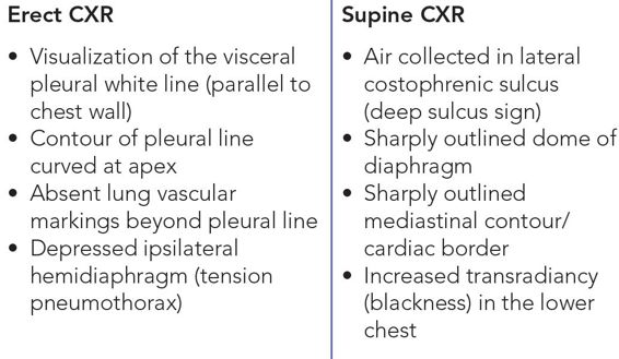
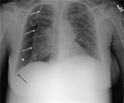
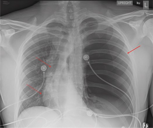
Table 1–4 and Figures 1–13 and 1–14 outline findings associated with pneumothorax. For the patient in extremis, tension pneumothorax is a surgical emergency requiring clinical diagnosis. However, in the transiently stable patient, findings on CXR significant for tension include:
Figure 1–13 AP upright CXR revealing a right pneumothorax. Note the increased lucency of the right hemithorax (asterisk) with deepening of the right costophrenic sulcus (black arrow) and loss of apposition between the pleural line and the chest wall (white arrows). The mediastinum and trachea are still midline, suggesting against tension.
Figure 1–14 Erect CXR showing large left tension pneumothorax (solid arrow). Note non-visualization of left hemidiaphragm due to depression and mediastinal shift (dotted arrows) to the right side. These two important signs are consistent with the diagnosis of tension penumothorax.
• Depression of the ipsilateral hemidiaphragm
• Mediastinal shift to the contralateral side
These two signs mandate emergent needle decompression, followed by thoracostomy tube placement.
Diaphragmatic Rupture
More common on the left side, bowel loops seen within the thorax with an ill-defined diaphragmatic contour suggest diaphragmatic injury. Chapter 28 discusses radiological recognition of this diagnosis in depth.
Esophageal Perforation
The typical patient presents with acute chest pain and has pneumomediastinum and increasing left pleural effusion on x-ray. Chapter 22 discusses this topic in detail.
Pulmonary Embolism
A normal CXR does not rule out pulmonary embolism. Clinical and laboratory findings dictate further imaging, usually with a CT pulmonary angiogram. However, a CXR is often the initial investigation in a breathless patient. Multiple CXR findings have been described in pulmonary embolism of varying specificity9 (Table 1–5 and Figure 1–15).
