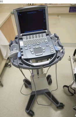
Figure 1.1 The evolution of ultrasound. When ultrasound was introduced, it was (a) a large apparatus that required (b) the immersion of a patient into a waterbath. (c) and (d) Current point-of-care ultrasound machines are portable and may be used at the patient’s bedside.
Point-of-care ultrasound provides the clinician with real-time, non-invasive data, making it an asset in the emergency and critical care departments. Its lack of ionizing radiation makes it particularly valuable for use in pediatric patients. For the abovementioned reasons, ultrasound is gaining momentum in the pediatric acute care setting as an adjunct to patient evaluation, as well as an adjunct for invasive procedures.
It is important for providers performing ultrasound to understand the basic concepts behind the complicated technology. Simply stated, ultrasound is based on sound waves and their physical principles. While audible sound is in the range of 20–20,000 Hertz (Hz), medical ultrasound uses sound waves in the range of 2–20 mega or million Hertz, MHz. Appreciating the fundamentals of ultrasound as well as the system functions, or “knobology,” will guide the clinician in better image acquisition.
Basic ultrasound principles, physics
The general principle of medical ultrasound is the “pulse echo principle,” which is best described using the analogy of sonar. SONAR, which is the acronym for sound navigation and ranging, is a technique based on sound propagation where devices generate and receive sound. For example, in submarine navigation, sonar capability allows a submarine to emit an acoustic pulse and then receive the returning sound after it strikes an object. Since the acoustic pulse has a known speed in a known medium (water), the elapsed “flight” time, the time from when the sound is transmitted to when it is received, can be used to calculate how far away the object of interest is located.
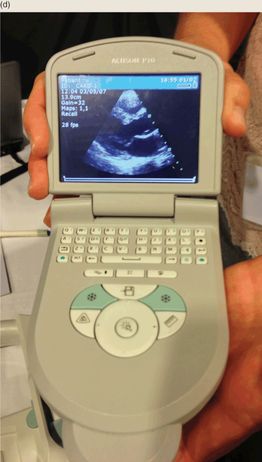
In medical ultrasound, the transducer emits pulsed longitudinal sound waves into the patient’s body and “listens” for returning echoes. The transducer contains ceramic crystals that, via the “piezoelectric effect” (Figure 1.2), convert electrical energy into mechanical energy (i.e. sound waves). Electricity is generated that vibrates the crystals to release sound waves at a speed of 1540 m/s, which is the average speed of sound in humans at body temperature. The transducer then listens for returning echoes, accounting for the time elapsed as well as intensity of the returning echoes. The returning sound vibrates the crystals and is converted back to electrical energy, to finally produce an image.
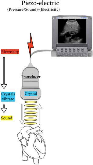
Figure 1.2 The piezoelectric effect. Electricity causes the crystals within the transducer to vibrate, creating sound. The sound reaches the organ of interest and returns to the transducer. The transducer spends 99% of the time “listening” to the returning sound waves. These are then converted into an image that can be seen on the ultrasound monitor. Illustration by Laura Berg, MD.
Sound is a form of mechanical energy that is characterized as a cycle of an upward and downward deflection. Frequency (Hertz, Hz) is the number of cycles that are repeated in one second. The amplitude (decibels, dB) is the height of the deflection and correlates with the “loudness” or intensity of the echo. The wavelength (mm) is the distance traveled in a single cycle (Figure 1.3).
Figure 1.3 The cycle of sound. Frequency (Hz) is the number of cycles repeated in one second, amplitude (dB) is the height of the deflection, and the wavelength (mm) is the distance traveled in a single cycle.
Attenuation
As ultrasonic waves travel through the body, the path and intensity of the sound change. Attenuation, which is the loss of energy, weakens the sound waves. Some energy is absorbed by the surrounding tissues and released as heat. Sound waves are also attenuated through reflection, refraction, and scattering. The degree to which the path changes is related to the acoustic impedance of the neighboring tissues through which it is traveling. Reflection is the redirection of the sound wave back to its source. Refraction is the redirection of part of the sound wave, as it crosses a boundary of two mediums with different propagation speeds. Scattering occurs when the sound waves encounter an irregular interface or one that is smaller than the sound beam. As sound waves encounter tissues of different densities, the path may be bent or refracted. The sound waves that are reflected back to the transducer are ultimately translated into an image.
Acoustic impedance
Acoustic impedance is the resistance of the tissue to molecular movement. Acoustic impedance is directly related to the density as well as the propagation of sound through that specific tissue. The greater the difference in acoustic impedance from one tissue to another, the louder the echo produced. Greater changes in acoustic impedance require more energy; thus, sound waves will have less energy to interrogate deeper structures. When the difference in acoustic impedance is the largest (i.e. soft tissue next to bone or air) this is referred to as acoustic mismatch. In this scenario, sound waves are scattered, and little information is reflected back to the transducer. In contrast, tissues with similar acoustic impedance allow sound to penetrate and interrogate deeper structures and are referred to as acoustic windows. The bladder is an example of an acoustic window.
Equipment
Transducers
Ultrasound transducers, or probes, are manufactured in assorted shapes and sizes (Figure 1.4). They are broadband devices that work over many frequencies. For example, the “abdominal probe” has a range from 2 to 5 MHz. The user can switch that transducer’s frequency to 2 MHz, 3 MHz, 4 MHz, or 5 MHz. The lower frequencies offer penetration, while the higher frequencies offer resolution.
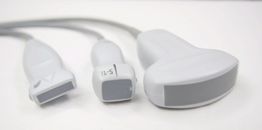
Figure 1.4 Various types of transducers.
The choice of a particular transducer should reflect the clinical indication and the patient population. Each transducer has a marker, or indicator, on it, correlating to a marker on the screen. This allows for proper orientation by the sonographer when performing and interpreting ultrasound (Figure 1.5). Spatial orientation is directly related to the transducer position and the two-dimensional plane being interrogated (see S2, Introduction).
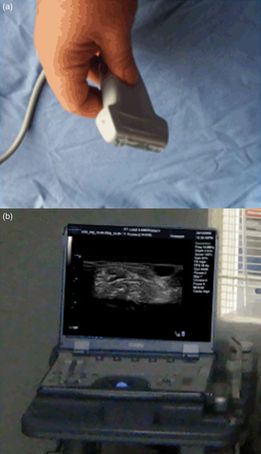
Figure 1.5 Indicator and screen orientation. (a) Each transducer has an indicator mark, which corresponds to the indicator mark on the ultrasound image. (b) In the standard views, the indicator corresponds with the left-hand side of the image.
A thorough investigation requires movement of the transducer. Fanning or sweeping of the transducer is accomplished by moving the transducer along an imaginary arc. Rocking the probe will tilt it, while rotating the probe is achieved by twisting the transducer clockwise or counterclockwise. Applying pressure on the transducer and pushing downward may displace bowel gas that interferes with image acquisition.
There are different types of ultrasound transducers: linear, curvilinear (or convex), phased array/sector, and endocavitary. They are characterized by shape, arrangement of the piezoelectric crystals, frequency range, footprint, and shape of the image produced. The footprint is the area of the transducer that comes in contact with the patient.
Linear transducers have a flat footprint that is rectangular in shape, and they therefore produce a rectangular image. The piezoelectric crystals are arranged in a linear fashion. There are various types of linear transducers that have different sized footprints; there is a particular linear transducer known as the “hockey stick” (Figure 1.6a). The frequency range varies among transducers and is approximately 5–10 MHz. Linear transducers often have higher frequencies, providing better resolution for shallow structures. However, with higher frequencies penetration and depth are sacrificed. These transducers are appropriate for visualizing superficial structures and as an adjunct for performing procedures such as vascular access, musculoskeletal applications, and abscess evaluation (see Section 3, Procedural ultrasound).
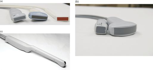
Figure 1.6 Transducers. (a) Linear high-frequency transducers. Note the different-sized footprints. The transducer on the right is a “hockey stick” linear transducer. (b) Low-frequency transducers used for cardiac and abdominal examinations. The transducer on the left is a phased array and the transducer on the right is the curvilinear. (c) Endocavitary transducer which is used for transvaginal ultrasonography and for the evaluation of peritonsillar abscesses.
Convex (curvilinear)-array transducers have a curved end (Figure 1.6b). They produce a sector-shaped image, with a curved area at the top. The piezoelectric crystals are arranged alongside one another along the curved face. These transducers have lower frequencies (2–5 MHz), allowing for better penetration of deeper structures. They are commonly used for the examination of the abdomen and pelvis. Smaller versions of the curvilinear transducers are referred to as microconvex, and have a smaller footprint that is especially useful in the pediatric population. Endocavitary transducers are a type of microconvex transducer with a long handle (Figure 1.6c). These transducers are appropriate for endovaginal evaluation of the female pelvis. Other indications include evaluation of the oral cavity; i.e. assessing peritonsillar abscesses.
Phased-array (sector) transducers have a flat end that is square or rectangular in shape, producing an image that is pie-shaped (Figure 1.6b). The piezoelectric crystals are grouped into a very small cluster and are steered electronically. These transducers emit lower-frequency (2–8 MHz) acoustic pulses and are useful for cardiac, thoracic, and abdominal imaging. Similar to the microconvex transducers, they have smaller footprints that are beneficial for pediatric scanning.
Monitors
Monitor considerations include flat-panel and cathode-ray tube monitors. Flat-panel monitors provide better image quality and are lighter, but also more expensive. Monitor size varies from 5 to 15 inches. Regardless of the type of monitor, it is important to remember to adjust the room lighting, in order to view images properly and identify subtle findings.
Maintenance of equipment
Ultrasound machines and equipment must be properly maintained. For the most part, transducers are extremely delicate. Care must be taken to not drop or damage them. Cracks in the crystals may appear as a vertical or horizontal line, depending on the type of transducer (Figure 1.7). Care must also be taken in cleaning the probes. A non-alcohol-based germicidal wipe may be used, or water and a non-abrasive soap. Note that when alcohol is used on the transducer footprint it may cause cracking. A cracked footprint should not be used on a patient, as it could expose both the patient and clinician to an electrical current. If footprint cracking occurs, the transducer should not be used and should be replaced. Special consideration should be taken in the sterilization of endocavitary probes. Due to the potential disruption of the barriers used, the transducers should be soaked in high-level disinfectants such as a glutaraldehyde product or Cidex OPA® solutions.
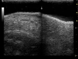
Figure 1.7 A damaged transducer. For the most part, transducers are extremely delicate. Dropping a transducer may result in a cracked crystal. In this linear transducer, there is a crack in a crystal, creating a vertical black line in the center of the image. When crystals are cracked, the transducer needs to be replaced.
It is not uncommon in the chaotic emergency department and critical care settings to overlook the maintenance of machines. Special care must be taken to avoid running over electrical and transducer cords. When a cord is frayed, it should be replaced and not used further.
Accessories
There are several accessories needed for successful ultrasound use. As previously discussed, the acoustic impedance of air makes ultrasound virtually impossible. Gel placed between the transducer and skin forms a barrier, thereby reducing air interference, and allowing the transmission of sound. Gels are made commercially, and standard gels are for external use only (Figure 1.8a). They should not be used if the integrity of the skin is compromised. Standard gels should also not be used in oral or endovaginal ultrasound as they can irritate the mucous membranes. A sterile sheath without overlying gel is sufficient and essential in performing endovaginal ultrasonography.
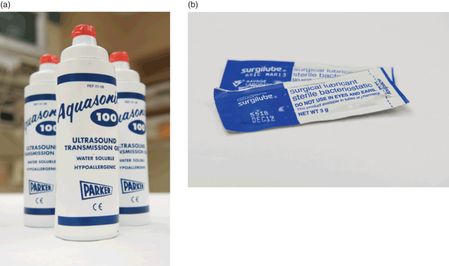
Figure 1.8 Gel. In order to transmit ultrasound waves, gel must be placed on the transducer footprint. (a) Commercially available gels are available, but are not sterile. (b) In order to maintain a sterile field while performing procedures, sterile lubricant may be utilized as an alternative.
When performing ultrasound-guided procedures, it is often necessary to maintain a sterile field. Commercially available sterile probe covers are available (see S3, Introduction). In order to properly prepare the transducer, a layer of standard gel is placed on it, followed by a sterile sheath, with sterile gel on top (see S3, Introduction). Sterile gel is manufactured and can be placed on top of the sterile sheath. Alternatively, a sterile lubricant may be utilized (Figure 1.8b). This type of set up is used for sterile procedures, including central line placement. In addition, many manufacturers offer a needle guide that attaches to the transducer to assist with ultrasound-guided procedures. These may be beneficial but are not a necessity.
Image storage
There are several options for image storage of both video clips and still images. Through a USB port, images can either be transferred to a flash drive, external hard drive or another computer. Some machines have a burner for CDs or DVDs, to which images can be stored. There are also the options of network storage, where images and videos can be transferred via an Ethernet port or WiFi and stored on a remote computer. Digital imaging and communication in medicine (DICOM) is the format that allows for transmission and storage of the images. This format is a standard among many departments and allows the user to manage the images within the available software applications. Disadvantages include the relative cost associated with DICOM packages and associated software. Lastly, images can be printed and stored as hard copies. Machines may come with either a black and white or color printer (Figure 1.9).
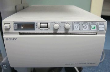
Figure 1.9 Ultrasound printer. Images may be stored digitally. However, a printed copy is often required for billing purposes.
Related posts:


Stay updated, free articles. Join our Telegram channel

Full access? Get Clinical Tree


