Percutaneous Neural Destructive Techniques
David Niv
Michael Gofeld
History
The idea of relieving intractable pain by severing a nerve as if it were a rope connecting an injured part with the brain probably originated in Descartes’ mechanical model of sensations; however, it took another 300 years to put this concept into practice. In his pioneering work La Chirurgie de la douleur, René Leriche proclaimed the term “pain surgery,” which eventually became a synonym of interventional pain management (1). He invented principles for operations on either sensory or autonomic parts of the nervous system to fight intractable pain. His most important contribution was probably the assertion of the concept of a “pain disorder.” Leriche wrote in his manuscript: “The disorder and its expression are confined within the nervous system. Localized in appearance, it affects virtually the whole individual” (1). Many years later, chronic pain would be defined as a disease in its own right (2). Even before surgical approaches emerged, descriptions of percutaneous methods of chemical ablation started to appear in the literature. Trigeminal ganglion ablation with absolute alcohol was first described by Härtel in 1912 (3). In 1926, Swetlow injected 85% alcohol paravertebrally in the upper thoracic level for the treatment of angina pectoris (4). Dogliotti described a technique of subarachnoid alcohol neurolysis for the treatment of sciatic pain in 1931 (5). Alcohol splanchnic nerve block was first described in 1957 (6), and several years later Brindenbaugh published the technique of neurolytic celiac plexus block for the management of cancer-related abdominal pain (7).
Interestingly, chemical neurodestructive procedures were mainly invented initially for the treatment of nonmalignant pain. The potential for devastating complications (8,9), the discovery of the sequelae of deafferentation pain (10), and especially the publication and overwhelming recognition of the gate control theory (11) diverted clinicians toward neuromodulation rather than neuroablation (see Chapters 40 and 41). Chemical neuroablation has fallen into disfavor and currently, with few exceptions, pertains to cancer pain management, where the limited life expectancy “protects” the patient from the development of deafferentation syndrome, and the loss of motor and sensory functions is perceived as an unfortunate but less important event (see Chapter 45).
The search for more predictable and localized neural destruction and fading interest in chemical ablation resulted in the invention of two physical approaches in the 1960s: radiofrequency (RF) neurotomy and cryoablation. Radiofrequency ablation of the Gasserian ganglion was described by Sweet and Wepsic and quickly became a well-accepted procedure, successfully concurring with results of alcohol and retrogasserian glycerol injections, but with fewer complications (12). Rapidly, several RF techniques were developed to treat various chronic pain conditions: spinal facet joint denervation, dorsal root ganglion lesion, percutaneous cordotomy, and sympathectomy (13,14,15,16,17).
At the same time, cryoanalgesia was introduced, initially to treat parkinsonism (18) and then to treat chronic pain. The idea of limiting lesion size within the boundaries of the target nerve, thus avoiding complications associated with inadvertent spread of the neurolytic solution, was so attractive that clinical applications of this method often preceded scientific knowledge. In fact, only a few randomized controlled studies were published on RF neurotomy of cervical and lumbar facet joints (19,20,21,22,23). The history of lumbar facet denervation merely mirrors the battle between clinicians’ desire to implement a new and virtually complications-free procedure and the lack of compelling knowledge of applied anatomy and physics. Positive results from randomized controlled trials (RCTs), in which selection criteria and surgical techniques were flawed, suggest another problem: namely, the difficulty of producing high-quality clinical trials in the field of neurodestructive procedures. Cervical facet neurotomy ran a more favorable course since its use was preceded by anatomic studies and only then followed by a carefully performed randomized controlled study by Lord and colleagues (23) that provided compelling evidence of efficacy. This study unequivocally demonstrated the benefit of an RF procedure performed using an anatomically correct approach. Therefore, any other technique should be considered as a nonvalidated method.
Obviously, clinical trials of interventional procedures have technical, methodological, and ethical restraints, especially in cancer pain management. Only neurolytic celiac block has shown a sufficient level of evidence (24) in comparison with conservative treatment. Evidence of efficacy is restricted to case series and case reports for other neurolytic procedures. Only one randomized trial was published comparing cryoanalgesia with phenol block of peripheral nerves, reporting slightly better results after phenol injection (25).
Current Situation
Notwithstanding the limited evidence of efficacy for many procedures, several percutaneous neural destructive techniques have earned a reputation as being reliable and effective. This chapter concentrates on describing techniques that can be recommended in routine clinical practice. Other procedures will be mentioned as a matter of curiosity and for the sake of comprehensiveness.
Table 42-1 Classification of percutaneous neural destructive procedures | |
|---|---|
|
The era of “blind” injections belonging to a small group of “experts” has passed. Neurolytic procedures must be performed under imaging guidance. This approach ultimately eliminates any question of technical error or misplacement of the needle or cannula and greatly reduces the rate of complications. In addition, visualization of the spread of radiopaque contrast before an ablation procedure or injection of a chemical agent can help predict anticipated effects and further decrease adverse outcomes associated with intravascular injection or a misplaced neuroablation device. Computed tomography (CT) and fluoroscopy are invaluable tools for cranial and spinal procedures, and ultrasonography has emerged as the standard tool for peripheral soft-tissue procedures.
Classification and Basic Principles of Percutaneous Techniques
Percutaneous neural destructive techniques can be classified according to application, methodology, and anatomy (Table 42-1). This chapter will be concerned with procedures for the relief of intractable pain by means of RF and cryoablation. Chemical neurolysis in nonmalignant pain will be highlighted as well. Injection of neurolytic agents for palliation of cancer pain is discussed in Chapter 45.
Percutaneous neurolytic techniques can be used in several ways to treat intractable pain (Table 42-1). Most obvious are the destructive techniques that interrupt transmission in pain pathways, such as neurectomy, rhizotomy, and destructive lesions in the spinal cord. However, percutaneous destructive techniques of autonomic pathways also have been developed. They target either sympathetic ganglion (thoracic sympathectomy) or preganglionic sympathetic fibers (splanchnic neurolysis). Thus, neurolytic procedures are divided into the destruction of nociceptive conduction or the destruction of autonomic pathways.
Methods are classified according to modality: chemical (alcohol, phenol, and glycerol) or thermal (heating, cooling).
Logically, the division of neurolytic approaches may be based on anatomic site: peripheral, central, and, separately, autonomic. This classification system allows stepwise neurolysis and also produces cessation of nerve conduction in that part of the nervous system that anatomically corresponds to the painful site.
Selection of Patients for Destructive Procedures
The selection of patients for procedures for the relief of pain is a complex, multidimensional process. First, all simpler methods of treatment must have been tried and found ineffective. Second, the proposed invasive procedure should have a reasonable chance of relieving the problem for which it is proposed, commensurate with the severity of the symptoms it is intended to relieve, the impact of the procedure, and the likely complications. Third, the patient and family should understand that the procedure is intended to control specific symptoms, not the underlying disease and other problems related to it. For instance, a procedure for pain caused by spinal cord injury does not affect the paraplegia. Fourth, it should be clearly recognized that procedures for pain relief seldom give permanent relief. Pain usually recurs in time no matter what operation is done (26), quite apart from early failure that may reflect waning of an initial placebo effect, which is usually more transient than a procedure-specific effect (27). Finally, destructive procedures for pain relief may give rise in themselves to iatrogenic neuropathic or deafferentation pain syndromes (28).
Prior to a neurodestructive procedure, a diagnostic trial of local anesthetic to block the nerve target must be carried out. Anesthesia of the potential source of the patient’s pain should provide almost complete pain relief for the duration of action of the specific analgesic or for longer than expected. Placebo-controlled blocks, considered as the gold standard in research applications, have been disproved for clinical practice because of both logistic and ethical concerns (see also Chapter 38). Deceptive use of a placebo is unethical, and a set of three diagnostic tests is probably overzealous and costly in a busy clinical practice. Comparative medial branches blocks recommended before RF zygapophysial neurotomy should be considered as an acceptable and validated method for any diagnostic spinal nerve injection (29,30). The main idea behind this strategy is to produce an unbiased response due to a patient’s unawareness of the type of local anesthetic injected. For instance, diagnostic workup of lumbar zygapophysial pain includes fluoroscopy-guided low-volume injections of the medial branches of the dorsal rami at the suspected levels. In the first block, 0.5 mL of 0.5% bupivacaine without epinephrine is injected at each target level. The patient has to complete a self-administered pain score diary and use a telephone answering system to report the degree and duration of pain relief according to a numeric pain score (from 0–10) before the procedure and every 30 minutes for up to 6 hours afterward. The response is considered positive if the patient experiences a decrease in numeric pain score of at least 80% for more than 3 hours.
Patients with a positive result after the first block undergo a second block on a separate occasion with 0.5 mL of 2% lidocaine. The same method is used to determine pain before and after the procedure. The block is determined successful if greater than 80% pain relief is obtained for more than 1 hour.
Radiofrequency facet denervation is proposed for patients who experience pain relief (according to the stated definitions)
in both diagnostic studies. Concordant response, in which the patient reports relief of pain for a shorter duration following lidocaine injection and for a longer duration after bupivacaine use, confirms the diagnosis with a confidence level of 85% (31). If the patient reports more than 80% pain reduction but with no appropriate differential response, this result should be interpreted as “discordant.” Nevertheless, discordant response provides a 65% level of confidence (31). Discrepant or negative response exists when the patient fails to obtain pain relief on a second confirmative block (see also Chapter 38).
in both diagnostic studies. Concordant response, in which the patient reports relief of pain for a shorter duration following lidocaine injection and for a longer duration after bupivacaine use, confirms the diagnosis with a confidence level of 85% (31). If the patient reports more than 80% pain reduction but with no appropriate differential response, this result should be interpreted as “discordant.” Nevertheless, discordant response provides a 65% level of confidence (31). Discrepant or negative response exists when the patient fails to obtain pain relief on a second confirmative block (see also Chapter 38).
Neural Destructive Procedures: Physical Principles and Biologic Effect
Wherever possible, RF lesion-making is the preferred procedure because of the ease of making a graded lesion of planned reproducible size (14,32,33) (Fig. 42-1). This is accomplished by controlling the diameter and length of the active tip of the cannula, the duration of current flow, and the tip’s temperature during lesion-making. Radiofrequency electrical current is a high-frequency (500-KHz) signal. A large positive electrode, a ground pad, is applied on the skin. Electric flow concentrates on a very limited area of the negative pole, the active tip. Oscillations of electrical current produce molecular friction and, therefore, elevation of temperature. If the active tip is equipped with a thermocouple, the temperature can be recorded. In addition, impedance of the tissue is usually monitored. A temperature of 45°C to 50°C is considered as a “minimal lethal margin” for biologic tissue. Obviously, higher temperature creates a bigger lesion; however, no further extension of lesion is found with the temperature higher than 80°C (33). Moreover, higher temperature can lead to charcoaling and boiling. Therefore, the routine temperature recommended is 80°C (Fig. 42-2). Similarly, lesion size depends on the size and shape of the active tip (Fig. 42-3). The maximal useful diameter is thought to be 15-gauge, since no further increase in lesion size occurs with a cannula bigger than that (33). Last, but not least, it is mandatory to place the cannula parallel to the target nerve, because the RF lesion is created from the sides of the cannula, not from the tip (34). The maximal lesion size is roughly two cannula diameters circumferentially (35).
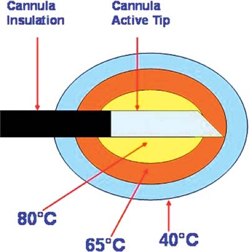 Figure 42-1. Diagram of a typical radiofrequency cannula with 80°C temperature setting. |
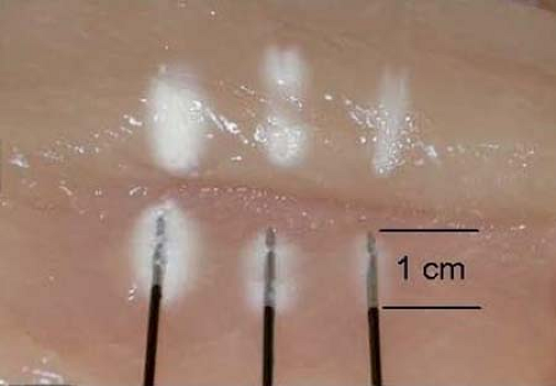 Figure 42-2. Radiofrequency lesion is increased by the temperature elevation. From left to right: 80°C, 70°C, and 60°C. Duration of lesion is 75 seconds. Courtesy of Baylis Medical Inc. |
An RF lesion-making generator usually includes other features, such as data recording, a nerve stimulator, and an impedance monitor, to facilitate control of the procedure (Fig. 42-4).
The technique of RF lesion-making is similar wherever applied, and details will be given here only for selected procedures. Most RF procedures are performed under local anesthesia with intravenous (IV) sedation. Care is taken to provide the necessary analgesia for the patient’s ongoing pain, but
not sufficient sedation to cloud the patient’s ability to cooperate with physiologic testing. The RF cannula is introduced toward the intended target under fluoroscopy or computed tomography (CT) guidance. When it appears to be in the correct anatomic location, this fact can be further corroborated in a number of ways. Contrast medium can be injected, then monitored under image intensification. Impedance monitoring is helpful, with levels of 400 Ohms being typical of cerebrospinal fluid (CSF), 800 to 1,200 Ohms typical of the spinal cord, and 100 to 400 Ohms being normally recorded during rhizotomies and neurotomies. If high resistance is encountered for the conventional musculoskeletal procedure, it can and must be reduced by injecting a small volume of normal saline or local anesthetic. Recording is also useful; microelectrode recording is probably limited to lesion-making in the brain or perhaps the spinal cord, but recording of evoked potentials is much more generally applicable. However, macro stimulation is most often applied for physiologic corroboration. Usually, threshold stimulation is applied at low (2 Hz for motor) and high (50 Hz for sensory) frequencies, and the responses are compared with ideal findings expected for the specific target. Once localization is deemed satisfactory, an RF lesion is made with parameters appropriate to the procedure.
not sufficient sedation to cloud the patient’s ability to cooperate with physiologic testing. The RF cannula is introduced toward the intended target under fluoroscopy or computed tomography (CT) guidance. When it appears to be in the correct anatomic location, this fact can be further corroborated in a number of ways. Contrast medium can be injected, then monitored under image intensification. Impedance monitoring is helpful, with levels of 400 Ohms being typical of cerebrospinal fluid (CSF), 800 to 1,200 Ohms typical of the spinal cord, and 100 to 400 Ohms being normally recorded during rhizotomies and neurotomies. If high resistance is encountered for the conventional musculoskeletal procedure, it can and must be reduced by injecting a small volume of normal saline or local anesthetic. Recording is also useful; microelectrode recording is probably limited to lesion-making in the brain or perhaps the spinal cord, but recording of evoked potentials is much more generally applicable. However, macro stimulation is most often applied for physiologic corroboration. Usually, threshold stimulation is applied at low (2 Hz for motor) and high (50 Hz for sensory) frequencies, and the responses are compared with ideal findings expected for the specific target. Once localization is deemed satisfactory, an RF lesion is made with parameters appropriate to the procedure.
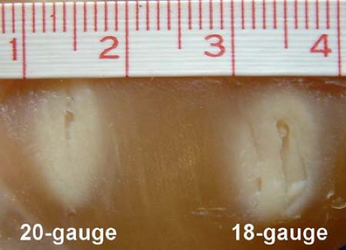 Figure 42-3. Two radiofrequency lesions were created with rotation of active tip in opposite directions. The maximal diameter of the lesion was measured: 18-gauge cannula produces 9-mm width burn, whereas 20-gauge creates only a 5.5-mm width lesion. |
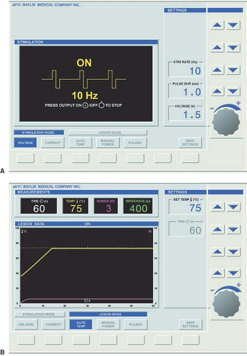 Figure 42-4. Radiofrequency generator monitor shows (A) stimulation mode and (B) lesion mode. Courtesy of Baylis Medical Inc. |
Cryoablation, the second physical modality for the treatment of pain, was implemented by Lloyd in 1976 (36). The cryoprobe consists of a hollow tube with a smaller inner tube (Fig. 42-5). Pressurized gas (usually nitrogen dioxide or carbon dioxide) at 600 to 800 PSI flows through the inner tube and
is released into the larger outer tube through a very fine aperture (0.002 mm). This process extracts heat from the tip of the probe, resulting in a temperature drop (Joule-Thompson effect) and formation of an ice ball, with temperatures in the range of –70°C (37). The gas is then scavenged through an outer tube. A 2.0-mm probe forms a 5.5-mm ice ball, and a 1.4-mm probe forms a 3.5-mm ice ball (Fig. 42-6). A cryoablation machine also includes a nerve stimulator, which allows precise localization of the target nerve, and some models include a thermostat for the temperature monitor (Fig. 42-7).
is released into the larger outer tube through a very fine aperture (0.002 mm). This process extracts heat from the tip of the probe, resulting in a temperature drop (Joule-Thompson effect) and formation of an ice ball, with temperatures in the range of –70°C (37). The gas is then scavenged through an outer tube. A 2.0-mm probe forms a 5.5-mm ice ball, and a 1.4-mm probe forms a 3.5-mm ice ball (Fig. 42-6). A cryoablation machine also includes a nerve stimulator, which allows precise localization of the target nerve, and some models include a thermostat for the temperature monitor (Fig. 42-7).
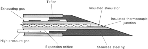 Figure 42-5. Details of cryoprobe tip. From Lloyd J, Barnard J, Glynn C. Cryoanalgesia, a new approach to pain relief. Lancet 1976;2:932–934. |
The application of cold to tissues creates a conduction block, similar to the effect of local anesthetics. At 10°C, larger myelinated fibers stop conducting, and at –20°C, all nerve fibers stop conducting. Long-term pain relief from nerve freezing occurs because ice crystals create vascular damage to the vasa nervorum, which produces severe endoneural edema and creates Wallerian degeneration, but leaves the myelin sheath and endoneurium intact (38). The Schwann cell basal lamina is spared and ultimately provides the structure for regeneration. Although demyelination and degeneration of the axon occurs, the intact endoneurium prevents neuroma formation, and the nerve is typically able to regenerate at a rate of 1.0 to 1.5 mm per week (39).
In comparison with RF, cryodestruction also provides satisfactory lesion-making, but it requires a rather larger probe that is easily damaged, a supply of liquid nitrogen, and a delivery system that is prone to blockage and other problems. Furthermore, cryosurgery is more time-consuming, requiring two to three freezing cycles of 3 minutes each at each target. Unlike the RF cannula, which usually does not require attention during the procedure, the cryoprobe must be kept steady by the operator, which may lead to fatigue and subsequent dislodgement.
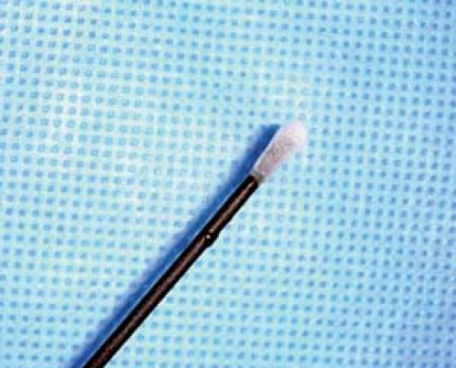 Figure 42-6. Ice-ball around the active tip of 12-gauge Lloyd cryoprobe. |
Multiple potential indications for cryodestruction have been reviewed recently, including treatment of craniofacial pain, thoracic and abdominal wall pain, pelvic pain, and spinal problems, as well as destruction of a peripheral nerve and neuroma (40). Unfortunately, cryoneurolysis usually fails to provide the lasting pain relief, usually fading within about 3 months. Furthermore, the level of evidence of efficacy of cryoablation may be defined as indeterminate to limited (level V to IV) (41) since the vast majority of available publications are nonexperimental descriptive studies and case reports. Only one randomized trial assessed the efficacy of cryoablation versus phenol block, and it showed better results in the phenol group (25). Nevertheless, because a thermal heat lesion is perceived to have high potential for nerve injury pain, cryoneurolysis could be recommended for the treatment of chronic pain wherever lesion of a peripheral nerve or neuroma is warranted.
Destructive chemicals also have been used extensively (42,43,44,45,46) in neurodestructive procedures. Absolute alcohol, phenol, and glycerol are most commonly used (Chapter 45); hypertonic and cold saline also have been used intrathecally (47). The introduction of chemicals has the advantage of applying a destructive agent that diffuses widely beyond the tip of the introductory needle, which is particularly useful when introduced into the CSF, say, in the Meckel cave or spinal canal. However, all these techniques have the disadvantage of erratic, unpredictable spread and variable degrees of penetration of nervous tissue; none is selective for pain fibers. They tend to produce incomplete and nonpermanent lesions. The danger of tracking is also significant; for example, alcohol injected into the infraorbital nerve may leak into the orbit and cause oculomotor palsy or blindness.
Percutaneous Neurectomy and Rhizotomy
Conceptually, percutaneous neurectomy or rhizotomy provide the simplest technique for treating pain syndromes that depend on pain transmission. Unfortunately, such procedures often are not useful either because pain is seldom restricted to the domain of one or a few nerves or roots, or because the inevitable concomitant sensory loss and/or motor impairment is not acceptable (48). Ineffectiveness of surgery on peripheral structures suggests that the source of the pain is to be found in central structures (49).
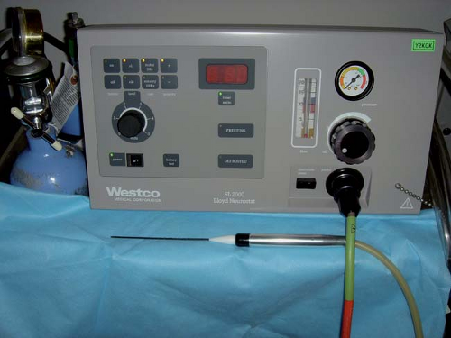 Figure 42-7. Cryoanalgesia machine. (Manufactured by Westco Medical Corporation.) |
Occipital Neurotomy
For pain syndromes amenable to treatment by denervation in the occipital nerve distribution, occipital neurectomy is commonly advocated. It can be accomplished using either RF or cryoablation. There is poor consensus on indications for occipital neurectomy, the procedure being advocated for diverse pain syndromes in occipital territory including occipital neuralgia, postherpetic neuralgia, and cervicogenic headaches (CH). The procedure should not be expected to relieve steady neuropathic pain, and conceptually it would not seem useful for the relief of pain caused by lesions proximal to the site of the denervation. It may be, however, that denervation of the projected field of the pain would prove to be effective treatment regardless of the site of the causative lesion, although it appears that no study of this issue has been undertaken. In a study of C2 ganglionectomy, microsurgical decompression of the C2 root and ganglion has some utility in treating CH. The accepted diagnostic criteria and success of anesthetic blockade of C2 should identify the subset of patients with CH predominantly caused by C2 root or ganglion effect at this level, which may favor surgical treatment (50). Although occipital neurectomy should eliminate the allodynia and hyperpathia of postherpetic neuralgia in C2–C3 territory by denervating the responsible receptors, this strategy is seldom worthwhile, since the steady element of the pain persists or may become worse as a result of deafferentation neuropathic pain.
Another condition in which occipital neurectomy has been recommended is occipital headache. Patients with recurrent attacks of headache located consistently in the same territory sometimes gain temporary relief from division of the peripheral nerves that supply the region of the head involved in the pain, including the occipital region.
The technique of percutaneous RF occipital neurectomy consists of introducing an RF cannula with an active tip 2 to 4 mm in length (Fig. 42-8) through the scalp to the expected location of the greater and/or lesser occipital nerves on the affected side at the base of the skull, using surface landmarks. Then 50-Hz stimulation is applied, and the needle is moved until paresthesia is produced in occipital nerve territory at the lowest threshold; an RF lesion is made and the degree of sensory loss is verified. Usually, a maximal lesion is required, achieved by several cycles of 80°C for 90 seconds.
It is difficult to present outcome data because these depend on the syndrome treated and the nature of the pain; reports fail to distinguish these matters. Published data suggest that 75%
of patients enjoy amelioration of occipital pain generally over a 1- to 4-year follow-up (51).
of patients enjoy amelioration of occipital pain generally over a 1- to 4-year follow-up (51).
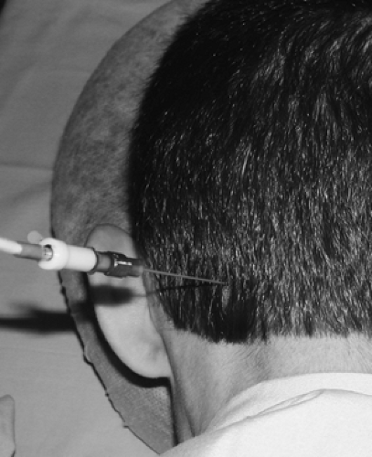 Figure 42-8. Greater occipital radiofrequency neurotomy of the left greater occipital nerve. 21-gauge 4-mm active tip cannula in place. |
Complications are few, with neuropathic pain in the denervated area being an ever-present concern. Recurrence after nerve regeneration is to be expected. Thus, the technique of suboccipital peripheral nerve stimulation has emerged as a preferable neuromodulatory technique (see Chapter 41).
Intercostal Neurotomy
Various pain syndromes, such as postherpetic neuralgia, postthoracotomy pain, intercostal neuralgia, and the pain of cancer, affect the chest wall. For these conditions, percutaneous RF intercostal neurectomy, first used by Tasker in 1972, may seem a promising procedure because it is not followed by significant functional deficit (52). However, comments made regarding occipital postherpetic neuralgia also apply to intercostal postherpetic neuralgia; and, for obscure reasons, intercostal neurectomy is practically useless in treating postthoracotomy syndrome, with only 25% of 44 patients reporting useful relief (52). Intercostal neuralgia usually results from compression of a thoracic root by a thoracic disk or foraminal stenosis, although sometimes no cause can be found. Because intercostal nerve section distal to a site of irritation is all that can be accomplished in treating intercostal neuralgia caused by disk compression or stenosis, this procedure appears to be ineffective. Destruction of the dorsal root proximal to the lesion site usually is necessary. Intercostal neurectomy is useful chiefly to treat pain caused by cancer of the chest wall; all of Tasker’s eight patients experienced relief when denervation of the painful area was possible and when the pain did not incorporate an old thoracotomy incision.
Chemical destruction is accomplished by injection of 1 to 2 mL of 10% phenol, using the same technique as that used for intercostal block with local anesthetic. Fluoroscopic guidance or ultrasonography is generally recommended to prevent inadvertent spread of the neurolytic solution into the epidural space.
Radiofrequency lesioning is usually performed under local anesthesia with fluoroscopy or ultrasound guidance. An 18-gauge RF cannula with a curved 10-mm active tip is “walked down” and slid under the inferior margin of the rib related to the nerve to be sectioned, proximal to the expected site of nerve involvement, until it enters or lies alongside the neurovascular bundle (see Chapter 16). Then, 2-Hz stimulation is performed as the needle tip is moved about, and contractions in the appropriate intercostal muscles are monitored until a site is found where the these contractions occur at 0.3 to 0.8 V. Two cycles of RF lesion are then made for 90 seconds, using a temperature of 80°C. It is wise to make a second lesion adjacent to the first to ensure adequate denervation. Efficacy is checked by ensuring that appropriate anesthesia has been achieved and/or by demonstrating increased threshold for motor response. An upright chest radiograph is performed immediately postoperatively to exclude pneumothorax, which occurred in approximately 3% to 6% of patients and required chest drainage in 2% (52).
Cryodenervation is also a feasible option. Local anesthesia of skin and intercostal space is performed with 1% to 2% lidocaine with 1:200 000 epinephrine. Epinephrine solution is useful for any cryoablation because it diminishes to some degree the bleeding associated with inserting a 12-gauge cryoprobe, and a spasm of blood vessels prevents the dissipation of cold. A Lloyd cryoprobe (12-gauge) is inserted so as to place the tip parallel to and under the corresponding rib (Fig. 42-9). Fluoroscopy may greatly help to place the probe accurately and avoid pneumothorax. Three cycles of freezing for 3 minutes each are executed, followed by slight advancement or retraction of the probe and duplication of the same process of freezing. Three consecutive lesions are sufficient for the ablation of the nerve. Spinal cord stimulation is often a better option in patients with neuropathic thoracic chronic noncancer pain (see Chapter 41).
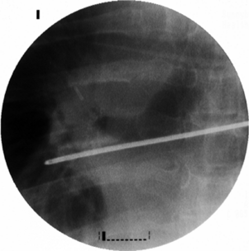 Figure 42-9. Intercostal neurotomy. Lloyd 12-gauge cryoprobe is placed in the medial-lateral direction and positioned below the rib. |
Miscellaneous Neurotomies
Several miscellaneous applications for peripheral nerve destruction have been published. Phenol neurolytic block of the suprascapular nerve and articular branches of the circumflex nerve was claimed to be effective in palliation of arthritic shoulder pain (53). Four patients obtained sustained pain relief after RF neurotomy of sensory branches of the obturator and femoral nerves for the treatment of nonoperable hip pain (54). Cryoanalgesia has been attempted in the treatment of painful peripheral nerve lesions (55). However, the risk of neuropathic pain is ever present.
Peripheral nerve destruction is occasionally recommended for the treatment of cancer pain (see Chapter 45) and spasticity. Discussion of the interventional treatment of spasticity is beyond the objectives of this chapter.
Dorsal Rhizotomy
According to Gybels and Sweet (56), Uematsu and his colleagues (15,57) were the first to report percutaneous RF dorsal rhizotomy. Although percutaneous RF dorsal rhizotomy has the advantage over neurectomy of not inducing motor deficits unless electrode positioning is faulty, and of usually denervating a larger area of the body, it still results in proprioceptive
loss, a serious problem if roots supplying limbs are sectioned. The fact that the radicular arteries that accompany roots may be end-arteries for the spinal cord—especially at the C1, T1–T4, and T11–L1 levels—means that their accidental occlusion may result in cord infarction and paraplegia.
loss, a serious problem if roots supplying limbs are sectioned. The fact that the radicular arteries that accompany roots may be end-arteries for the spinal cord—especially at the C1, T1–T4, and T11–L1 levels—means that their accidental occlusion may result in cord infarction and paraplegia.
Although experience with open rhizotomy has been extensively published, outcome data for the percutaneous technique are limited. In general, the pain syndromes for which dorsal rhizotomy should be considered are nociceptive pain caused by cancer or by spinal pathology that compresses nerve roots and the evoked or neuralgic elements of neuropathic pain. Control of malignant pain is limited to cases in which the entire area involved can be denervated by rhizotomy lesions that lie proximal to the tumor site. In practice, this is rarely practicable.
Radiofrequency dorsal rhizotomy for radicular pain is currently an ill-defined procedure, with the results of clinical trials mixed. Several observational studies found the procedure effective in the long term for about 50% of patients (58,59,60). Surprisingly, the complication rates of a new neuropathic pain, sensory loss, and motor loss were low. Painful dysesthesia was observed in 4% of patients (10), but it disappeared after 6 weeks. One RCT of cervical dorsal root RF rhizotomy showed clearly beneficial results in favor of RF treatment, but the follow-up was shorter than 8 weeks (61). Another RCT failed to prove the efficacy of RF posterior rhizotomy in treating lumbosacral radicular pain (62); however, this study contained several methodological and statistical biases (63). Currently, the procedure should only be considered for those patients suffering severe radicular pain when alternative nondestructive methods (multimodal medical treatment, fluoroscopy-guided epidural injection, spinal cord stimulation, and rehabilitation strategies) have failed and the patients are not candidates for neurosurgical correction of underlying pathology. Patients must understand the temporal nature of the treatment and its potential complications, including sensory and motor loss and dysesthetic pain.
Even when a single root can be incriminated by careful selective local anesthetic root blocks, the permanent rhizotomy may fail because the lesion cannot be made proximal to the site of entrapment or irritation. Also, because of innervation overlap within somatic areas, lesioning of a single nerve root may produce only temporary denervation. In patients with neuropathic pain in whom allodynia or hyperpathia are prominent features, rhizotomy may also be useful, as in cases of spinal cord injury with a radicular distribution of allodynia at the level of the cord lesion. If a limb is to be denervated, even with a single-level rhizotomy, the accompanying loss of position sense must be considered, and this is best assessed at the time of the essential diagnostic root blockade. However, such diagnostic blocks do not correlate precisely with the outcome of rhizotomy (see Chapter 38). Multiple consecutive rhizotomies are even riskier.
Notwithstanding the discretion needed in administering RF posterior rhizotomy for radicular pain, the procedure seems to be highly effective for the treatment of spasticity (64,65), producing an improvement in 94% of patients, with excellent results in 73%.
The technique consists of identifying the correct root(s) to be denervated by clinical means and diagnostic local blocks. Then, with the patient either under neuroleptic analgesia or local anesthesia or both, a 20-gauge RF cannula with a 5-mm active tip is introduced into the dorsal portion of the appropriate intervertebral foramen, under intermittent fluoroscopic guidance. Sensory stimulation, first at 50 Hz, should elicit tingling sensation at the corresponding dermatome, with a threshold of 0.3 to 0.5 V. Motor stimulation at 2 Hz must not produce muscle twitching below the level of the double sensory response current (i.e., if the patient experienced paresthesia at 0.5 V, one should avoid starting RF lesion if the motor response obtained was below 1 V). This strategy prevents inadvertent damage of the ventral motor portion of the nerve root. Traditionally, a temperature of 67°C, applied for 60 to 120 seconds, has been recommended for the RF dorsal rhizotomy.
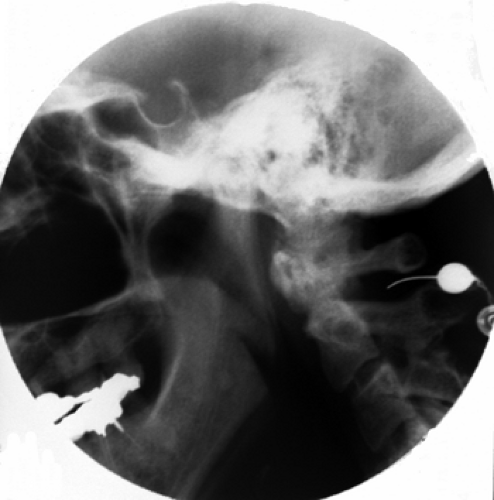 Figure 42-10. C2 dorsal root ganglion rhizotomy. Radiofrequency cannula is introduced at the border of the anterior third, within the posterior two-thirds of the atlanto-axial arch. |
Cervical Dorsal Rhizotomy
At the C2 level, the cannula should be introduced at the border of the anterior third with the posterior two-thirds of the atlanto-axial arch seen on the lateral view (Fig. 42-10). On the anteroposterior (AP) view, the tip should be seen at the middle of the atlanto-axial joint shadow (Fig. 42-11). Further insertion may result in dural puncture and spinal cord injury.
Placement of the cannula at any other cervical level is accomplished by using the oblique position of the image intensifier to “open up” the intervertebral foramina. Under tunnel vision, the cannula is aimed toward the posterior border of the foramen at its inferior third. After bone contact is made, the AP view is obtained and the cannula further introduced until positioned at the middle of the facet joint shadow. Often, the correct cannula position is heralded by paresthesia. Caution has to be taken not to introduce the cannula into the anterior portion of the foramen lest the vertebral artery be damaged.
Thoracic Dorsal Rhizotomy
At the thoracic levels, the cannula should be introduced into the superior portion of the intervertebral foramina in tunnel view. The AP image should confirm the position of the tip at the level of the facet joint line (Fig. 42-12).
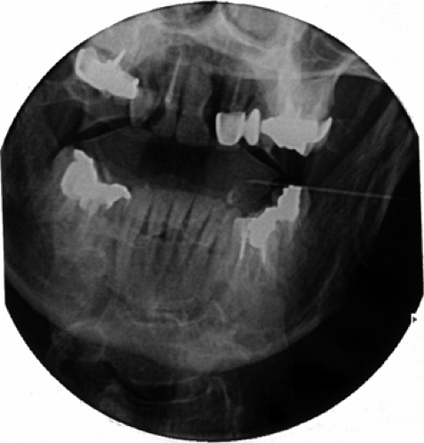 Figure 42-11. C2 dorsal root ganglion rhizotomy. Cannula tip is seen at the middle of the atlanto-axial joint shadow. |
Lumbar Dorsal Rhizotomy
In the lumbar area, the cannula is introduced into the dorsal third of the foramen using a tunnel view with approximately 30 to 40 degrees of lateral rotation. As a rule of thumb, the shadow of the spinous process should superimpose the contralateral facet joint. In this position, the cannula is aimed under the “chin on the Scotty-dog” (Fig. 42-13). In the AP view, similar to the thoracic levels, the tip of the cannula should be seen at the facet joint line. If, at the L5 level, a tunnel view often cannot be achieved because of the superimposed iliac crest, the cannula is introduced laterally and inferiorly into the space between the transverse process of L5 and the ala of the sacrum, aimed at the neck of the L5 transverse process. Progress is often impeded here by “sacralization” of L5 and/or osteophytes. Sacral ventral roots are reached through appropriate posterior sacral foramina, bringing the electrode tip to the anterior foramina. Here, one must be alert to the risks of causing bladder and sexual dysfunction.
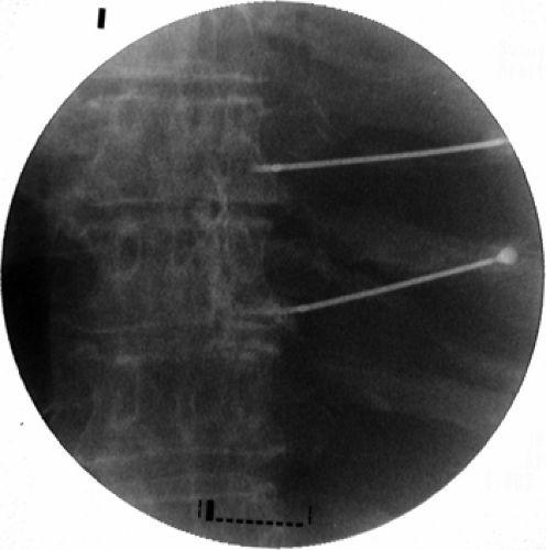 Figure 42-12. Thoracic dorsal root ganglions radiofrequency rhizotomy. Two 20-gauge 10- mm curved active tip cannulae are positioned (anteroposterior view). |
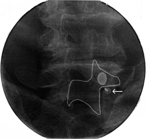 Figure 42-13. Radiofrequency rhizotomy of the fifth lumbar dorsal root ganglion. The cannula is positioned under “tunnel vision” fluoroscopy immediately laterally to the apex of the S1 superior articular process (under the “chin of the Scotty dog”). |
Uematsu and colleagues (15,57) reported seven excellent and two good results out of 17 patients operated upon for various pain syndromes. Pagura (66) reported 76% pain relief in 50 patients, 13 suffering from cancer and 37 from intervertebral disk disease, with a 4% incidence of temporary postoperative paresis.
Dubuisson (67) lists the data quoted in Table 42-2. Of the patients reported by van Kleef and colleagues (68), 13 suffered from degenerative disk disease in the C4–C6 region; of these, 75% enjoyed pain relief after 3 months and 50% after 6 months. Not unexpectedly, dysesthetic burning from iatrogenic deafferentation occurred in 12 patients (60%) but did not persist past 3 weeks; decreased sensation was seen in seven (35%) but disappeared after 6 weeks; no motor or reflex deficits were seen.
In the published data collected by Gybels and Sweet (56), of 192 patients with nonmalignant pain, 69% were enjoying useful pain relief; of six with pain caused by cancer, all were relieved. Follow-ups for these patients were short.
The complications of rhizotomy, other than failure and pain recurrence, include sensory and motor loss, iatrogenic neuropathic pain, and the risk of direct spinal cord damage or ischemic infarction due to injury of the radicular artery. These complications explain why few patients undergo rhizotomy,
but rather are treated with less-invasive methods including spinal cord stimulation (see Chapter 41).
but rather are treated with less-invasive methods including spinal cord stimulation (see Chapter 41).
Table 42-2 Results of percutaneous RF dorsal rhizotomy | ||||||||||||||||||||||||||||||||||||
|---|---|---|---|---|---|---|---|---|---|---|---|---|---|---|---|---|---|---|---|---|---|---|---|---|---|---|---|---|---|---|---|---|---|---|---|---|
| ||||||||||||||||||||||||||||||||||||
Spinal Zygapophysial Joint Neurotomy
This category of percutaneous nerve destruction is probably the most extensively published and clinically applied. Prevalence of zygapophysial joint pain is high, estimated as the source of pain in 15% to 45% of a heterogeneous group of patients with chronic low back pain, 42% to 48% of patients with thoracic pain, and 54% to 67% of patients with chronic neck pain. Individuals younger than 65 have lower incidence of facet joint pain (30%), whereas those older than 65 have higher prevalence (52%); males are slightly less affected (38%) as compared with females (43%) (69).
Prior to zygapophysial nerve destruction, the diagnosis must be confirmed by double comparative local anesthetic blocks, as described earlier. Multiple potential pain generators could be involved in spinal pain, including intervertebral disks, spinal nerves, and adjacent structures, and nonorganic components may play a significant role; therefore, establishing the correct diagnosis of the facet pain is imperative.
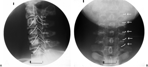 Figure 42-14. A: Lateral radiograph with diagram of surgical anatomy of cervical medial branches and the third occipital nerve. TON, the third occipital nerve; arrows, medial branches; asterisks, ventral cervical rami. B: Posteroanterior radiograph with drawing of the medial branches of C3–C7 at the middle of corresponding articular pillars (arrows). TON cannot be drawn on this figure because of mandible shadow. |
Cervical Zygapophysial Joint Neurotomy
The neurotomy technique for C3 to C7 medial branches was originally described by Lord and colleagues, and this is the only time it was validated in a RCT (23). More recently, an acceptable method of third occipital neurotomy was also described, but it has not been validated in a RCT (70). Medial branches of C3 to C6 take off from dorsal rami and are uniformly found at the waist of corresponding articular pillars. The third occipital nerve (TON) is in fact the posterior ramus of the third cervical root, much thicker than the ventral ramus. It usually lies on the line of C2–C3 facet joint or, alternatively, may be located slightly above or below the joint (Fig. 42-14).
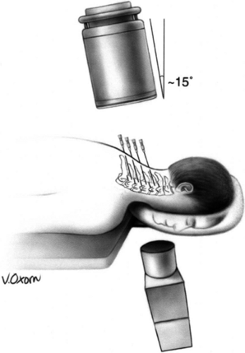 Figure 42-15. Cervical medial branch neurotomy (prone position). Patient placed prone with face on a padded ring. Image intensifier positioned anteroposteriorly and tilted 15 degrees caudad. Note: If the neck remains somewhat extended on a flat table, the caudad angulation must increase to 25 to 35 degrees (see Chapter 44, Fig. 44-28). Reprinted from Faclier G, Kay J. Cervical facet radiofrequency neurotomy. Tech Reg Anesth Pain Manage 2000;4:120–125, with permission. |
Here, we describe the method used for cervical facet neurotomy from the TON to the C7 medial branch (71). The most important recommendation is to place the cannula parallel to the target nerve at the anatomically correct area of the cervical spine.
The patient is positioned prone on the fluoroscopy table, with the head flexed 5 to 10 degrees in a soft frame (Figs. 42-15 and 42-16). Arms are positioned alongside the patient’s body, and shoulders are pulled on a caudad direction. Application of adhesive tape on the trapezius areas facilitates shoulder traction and helps to maximize the operator’s comfort and fluoroscopic visualization of the lower cervical vertebrae at the lateral view. Conscious sedation and local anesthesia with 2% lidocaine are sufficient to alleviate discomfort and to allow operator–patient communication. Under AP fluoroscopic view, the lateral masses of facet joints are seen. Recognition of the target level can be facilitated by either cephalo-caudad or caudo-cephalad tilt of the image intensifier. At the C1–C2 levels, the dens of C2 and the line of the atlanto-axial joint are useful landmarks. At the C2–C3–levels, the line caudad to the atlanto-axial joint is the C2–C3 facet joint, which is the target for the third occipital neurotomy. The waist of each lateral mass is the landmark for medial branch neurotomy (Fig. 42-14B). Alternatively, the C7 vertebra, with its wide transverse process, is used as the starting point to count more cephalad cervical vertebrae. At times, the mandible and the dentition may obscure the view. On such occasions, the patient’s head should be gently and slightly rotated contralaterally, and the patient asked to open the mouth.
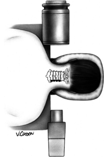 Figure 42-16. Cervical medial branch neurotomy (prone position). Patient placed prone with face on padded ring. Image intensifier rotated to the lateral position. Reprinted from Faclier G, Kay J. Cervical facet radiofrequency neurotomy. Tech Reg Anesth Pain Manage 2000;4:120–125, with permission. |
Universally, the skin entry point is chosen somewhat laterally to the bone at the level of a facet joint below the target (i.e., if the C4 medial branch has to be coagulated, the entry point should be 1.0–1.5 cm lateral to the C5–C6 facet joint). This routine allows cannula placement parallel to the nerve. A 22-gauge 5-mm RF cannula is inserted in a mesiad and cephalad direction to contact the facet nerve at the waist of each articular pillar (Fig. 42-17). For the third occipital neurotomy, the cannula is inserted to contact the midpoint of the C2–C3 facet joint line.
An alternative approach is to obtain a sublaminar AP view at a position that allows radiographic separation of facet joints. Since the sagittal line of the facet joints is parallel to the medial branch at the corresponding waist of the pillar, this fluoroscopy view secures insertion of the cannula parallel to the nerve. With a slight oblique rotation of 5 to 10 degrees, the skin entry point is superimposed on the midpoint of the pillar waist edge, and the cannula is positioned using “tunnel vision” technique until it makes contact with bone (Fig. 42-18).
The lateral view then confirms that the cannulae are in proper position and do not project anteriorly to the pillar (Fig. 42-19). A thermocouple electrode is inserted into the lumen of each cannula and stimulated with frequencies of 50 Hz (sensory) and 2 Hz (motor) (Fig. 42-20). The patient should experience a tingling sensation covering the painful area, but no radicular distribution. Usually, contractions of multifidus
muscles are seen during the motor stimulation. Another approach, with the patient positioned on the side, is discussed in Chapter 44 (see Fig. 44-30 and 44-31).
muscles are seen during the motor stimulation. Another approach, with the patient positioned on the side, is discussed in Chapter 44 (see Fig. 44-30 and 44-31).
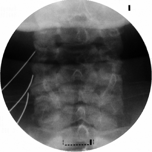 Figure 42-17. Cervical medial branch neurotomy (prone position). Anteroposterior view shows cannulae positioned at the waist of left cervical facet pillars C3, C4, and C5. The lower cannula seemed to be displaced, however this radiographic picture is misleading due to severe deformation of the articular pillar of C5. |
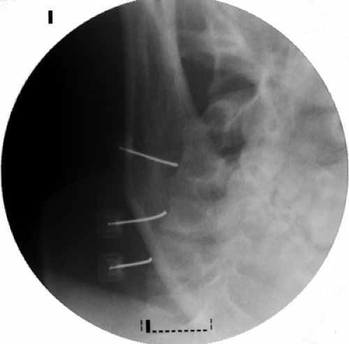 Figure 42-18. Cervical medial branch neurotomy (prone position). Anteroposterior view with caudo-cephalad tilt. The entry point is superimposed on the middle of the pillar waist edge, and the cannulae are positioned using the “tunnel vision” technique. |
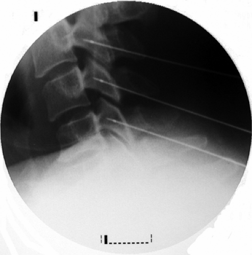 Figure 42-19. Cervical medial branch neurotomy (prone position). The lateral view confirms the proper cannulae position at the middle of the waists of C3, C4, and C5 articular pillars. The cannulae are positioned parallel to the target nerves and do not project anterior to the pillar. Radiopaque bead highlights the proximal end of active tip. |
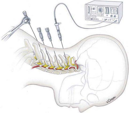 Figure 42-20. Cervical medial branch neurotomy (prone position). Lateral view shows ideal positioning of radiofrequency cannulae adjacent to the target nerves at the C2–C3 joint and C4 and C5 pillars. A cannula is being inserted to contact the C6 pillar. A thermocouple electrode has been inserted into the C2–C3 cannula in preparation for stimulation and radiofrequency neurotomy. Reprinted from Faclier G, Kay J. Cervical facet radiofrequency neurotomy. Tech Reg Anesth Pain Manage 2000;4:120–125, with permission. |
Following appropriate responses to stimulation, 0.5 mL of 2% lidocaine or 0.5% ropivacaine is injected through each cannula to abolish pain during the RF lesion, which is made at 80°C for 60 seconds. With proper anatomic position and concordant stimulation, two cycles of lesion are sufficient for the medial branch neurotomy at C3 to C7. However, two or three consecutive lesions, made by repositioning the cannula cephalad and caudad, were recommended in the original article published on this technique (23). At the level of C2–C3 (TON), three lesions are executed: at the level of the joint, immediately above it, and then below the joint line on the lateral view. The TON is the thickest, and its pathway is variable. Depending on the electrical stimulation, occasionally a lesion at the level of the joint and two additional burns above or below the joint are required.
Usually, RF neurotomy is performed at a minimum of three levels that correspond to the patient’s pain. Suboccipital pain and headaches require third occipital neurotomy and C3 and C4 medial branch neurotomies. Neck pain with radiation to the upper trapezius needs to be addressed by C4 to C6 neurotomies, whereas pain referred to the shoulder and scapula requires C5 to C7 neurotomies.
Fluoroscopic control, proper cannula placement, and the use of stimulation before nerve destruction make complication rates fairly low. However, if RF inadvertently damages the posterior ramus and/or its lateral branch, cutaneous dysesthesia and sometimes anesthesia can result, but this usually resolves within 3 to 4 months. In Lord’s study, five of 12 patients had numbness or dysesthesia in the cutaneous territory of the coagulated nerves, but they did not rate it as a troublesome or requiring treatment (23). The TON supplies cutaneous sensation over a small area of the occiput. Thus, numbness and neuritic pain may occur in the area around the suboccipital region and usually resolves within weeks to months. Rarely, if the procedure fails to provide pain relief, some patients may report transient escalation of their pain. Failure of the procedure may be a result of poor patient selection, missing the target nerve, proximity of blood vessels close to the tip of the cannula producing a heat sink, a relatively small burn area compared with the local anesthetic coverage, or alternate afferent pathways.
Thoracic Zygapophysial Joint Neurotomy
The anatomic basis for this procedure has been investigated in a cadaveric study (73). At the upper (T1–T3) and lower (T9–T10) levels, the medial branch consistently passes across the intertransverse space, making contact with the lateral end of the superior border of the transverse process (Fig. 42-21). The T11 medial branch passes across the base of the superior articular process (SAP) of T12. The T12 medial branch runs similarly to the lumbar levels (see next section). At midthoracic levels (T4–T8), the course of a medial branch is less constant. Usually, at these levels, the nerve passes somewhere in the intertransverse space without making contact with bone.
Prior to neurotomy, double comparative local anesthetic block should establish the diagnosis of thoracic facet pain. Although medial branch anesthetic block is a simple and straightforward technique, the situation is completely different for the performance of RF neurotomy. No validated technique has been published yet. Only one published prospective observational study of 40 patients claimed some benefit, reporting good to excellent pain relief for an average duration of 31 months, but the method used cannot be considered as anatomic (74).
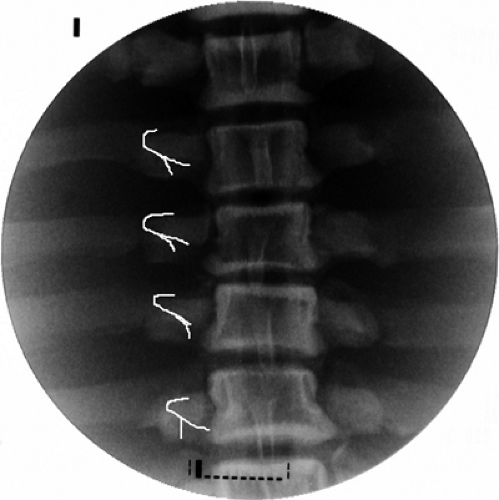 Figure 42-21. Thoracic medial branch neurotomy (prone position). Drawing (white lines) on the radiographic image shows upper thoracic medial branches emerge through intertransverse space, make contact with the lateral end of the superior border of the transverse process, and continue in mesiad-caudad direction. |
In theory, contralateral cannula insertion should align the position of the active tip parallel to the target nerve. The authors follow this principle in clinical practice in the neurotomy of T1 to T3 and T9 to T10 (Fig. 42-22); however, we refrain from recommending it before a formal validation study is performed. T11 and T12 neurotomies are performed similarly to those at the lumbar levels (see next section).
Lumbar Zygapophysial Joint Neurotomy
The anatomy of lumbar zygapophysial nerves and the position of RF cannulae are illustrated in Figure 42-23. Each facet joint is innervated by two nerves: the medial branch of the dorsal ramus at the same level and from the level above, excluding the L5–S1 facet joint, which is thought to be innervated by the L4 medial branch and the L5–S1 dorsal rami. All lumbar medial branches and the L5 dorsal ramus pass the base of the superior articular process (SAP) between the intervertebral foramen and the mamillo-accessory ligament (75,76). The S1 posterior ramus leaves the S1 posterior foramen at 12 o’clock, sending the ascending branches to innervate the L5–S1 facet joint (77).
The principle of lumbar zygapophysial joint neurectomy is the same as for the other areas: placement of the RF cannula parallel and adjacent to the target nerve.
Facet neurotomy is performed under local analgesia and light neuroleptic anesthesia. The patient is placed in the prone position on a fluoroscopy table with a pillow under the abdomen to alleviate lumbar lordosis (Fig. 42-24). The AP
fluoroscopic view is obtained with maximal exposure of the target points. Lidocaine 2% or ropivacaine 0.5% is used for the local anesthesia. The selected skin entry point is somewhat lateral to the pedicle, one level caudal for every lumbar level, excluding L5 and S1. For the L5 dorsal ramus, the entry point is approximately at the level of the S1 posterior foramen, but less laterally than for the upper levels, so as not to superimpose the iliac crest on the sacral ala. For the S1 level, a tunnel view of the posterior neural foramen is obtained. The entry point is situated at the 12 o’clock position of the foramen (Fig. 42-25; see also Chapter 44, Figs. 44-34,44-35,44-36,44-37).
fluoroscopic view is obtained with maximal exposure of the target points. Lidocaine 2% or ropivacaine 0.5% is used for the local anesthesia. The selected skin entry point is somewhat lateral to the pedicle, one level caudal for every lumbar level, excluding L5 and S1. For the L5 dorsal ramus, the entry point is approximately at the level of the S1 posterior foramen, but less laterally than for the upper levels, so as not to superimpose the iliac crest on the sacral ala. For the S1 level, a tunnel view of the posterior neural foramen is obtained. The entry point is situated at the 12 o’clock position of the foramen (Fig. 42-25; see also Chapter 44, Figs. 44-34,44-35,44-36,44-37).
 Figure 42-22. Thoracic medial branch neurotomy (prone position). A 18-gauge 10-mm curved active tip radiofrequency cannula is inserted from the level of the spinous process and directed toward costo-transverse junction. Active tip is parallel to thoracic medial branch nerve. White drawing delineates the transverse and superior articular processes of thoracic vertebra. |
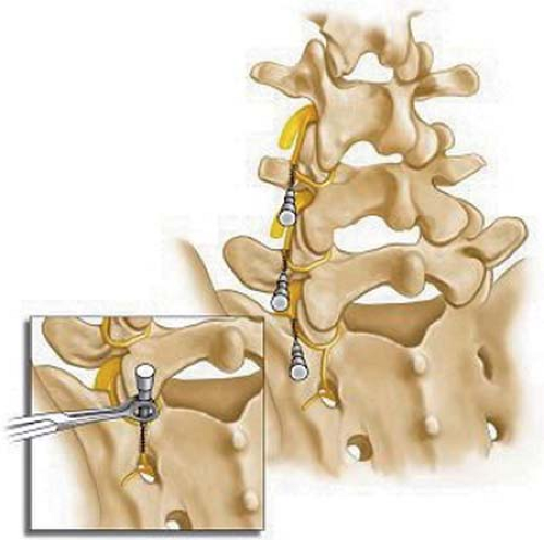 Figure 42-23. Lumbar medial branch neurotomy (prone position). The medial branches of L3 and L4 and the posterior primary rami of L5 and the first sacral vertebra (S1), with cannulae placed parallel to the nerves (S1 inset). |
An 18-gauge cannula with a curved 10-mm active tip is probably the best suited disposable device for this application. Although the best published results (78) were reached when a 15-gauge solid Ray electrode was used, the lack of available supply of that device and the fact that it is not disposable make an 18-gauge single-use cannula a suitable alternative. A 10-mm active tip completely corresponds to 1 cm of exposed nerve before it disappears under the mamillo-accessory ligament.
Standard Technique
The cannula is inserted and advanced toward the target using intermittent AP fluoroscopy. Several steps are taken to ensure placement of the cannula at the correct final position at the base of the corresponding SAP. First, the contact with bone is made just caudal to the superior edge of the transverse process (or the sacral ala for L5), immediately lateral to the base of the SAP (Fig. 42-26A; see also Chapter 44 Figs. 44-37 and 38).
The image intensifier is then rotated to the lateral view. The cannulae are advanced until loss of bony contact is felt and seen on fluoroscopy. Lateral views are used to ensure that the tip of the cannula did not pass the posterior boundary of the intervertebral foramen but is situated close to the anterior border of the SAP (Fig. 42-26B).
The 10- to 20-degree oblique view is used to demonstrate correct cannula placement parallel to the base of the SAP. The cannula tip is obliquely crossing the shadow of corresponding pedicle in this projection (Fig. 42-27).
At the S1 level, the cannula is introduced at the 12 o’clock position while constant bony contact is maintained. A lateral view is used to verify the position of the cannula tip outside the sacral canal (Fig. 42-28).
Finally, electrical stimulation at 50 Hz is performed for sensory testing; a dermatomal pattern is considered unacceptable. A frequency of 2 Hz is then applied for motor stimulation. Any motor response other than twitching of the multifidus muscles must be interpreted as stimulation of the ventral ramus. In this situation, the cannula must be repositioned, usually by slight withdrawal, until no dermatomal or motor response is obtained.
A small volume (0.5–1.0 mL) of local anesthetic is injected before activation of the RF generator. The first lesion is created with the cannula tip rotated caudally, following the curvature of the bone (7 o’clock for the right and 5 o’clock for the left side). The duration of the cycle is 90 seconds with 80°C temperature. The second lesion is generated after dorsal rotation (11 o’clock for the right and 1 o’clock for the left side), moving up on the SAP, to increase the size of the lesion. This rotation is warranted because variations in the path of the medial branch occur in the caudo-cephalad direction on the surface of SAP.
S1 dorsal ramus RF neurotomy is performed with the same parameters. The cannula’s active tip, initially faced cephalad (12 o’clock), is rotated to 2 o’clock and the first lesion created. The second lesion is performed at the 10 o’clock position.
Tunnel Vision Technique
The principle of this technique is to insert RF cannulae under fluoroscopic tunnel vision guidance, avoiding the difficulties of
two-dimensional vision inevitably encountered with the technique described earlier for the L1 to L5 levels.
two-dimensional vision inevitably encountered with the technique described earlier for the L1 to L5 levels.
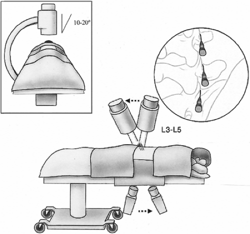 Figure 42-24. Lumbar medial branch neurotomy (prone position). Diagram showing patient’s position and cannulae placement at the L3–L4, L4–L5, and L5–S1 levels. If image intensifier is tilted caudo-cephalad (arrows), the radiographic anteroposterior view becomes sublaminar “tunnel vision” view. |
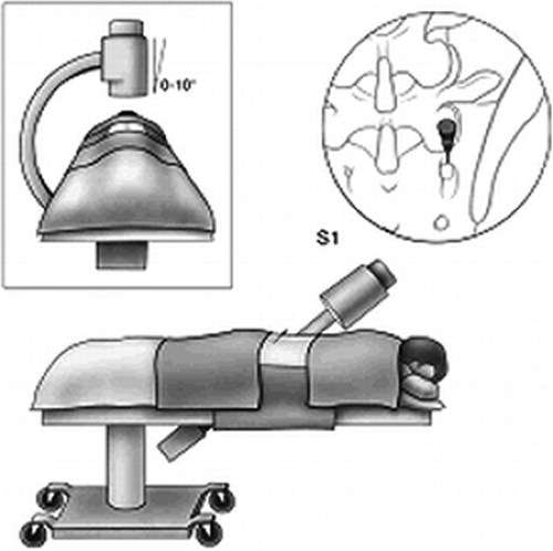 Figure 42-25. S1 medial branch neurotomy (prone position). Position of patient, fluoroscopic image intensifier, and site of the cannula placed at the foramen for S1 dorsal ramus neurotomy. |
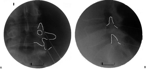 Figure 42-26. Lumbar medial branch neurotomy (prone position). A: Anteroposterior view shows cannulae at the L4–L5 and L5–S1 levels. The tip of the cannula is positioned at the junction of the superior articular process and the transverse process/sacral ala. B: Lateral view shows that the cannula tip remains within the shadow of the base of the superior articular process, parallel to the medial branch and L5 dorsal ramus. |
First, a lateral image of the lumbar spine is obtained. The scout image of the target segment is printed, and the angles between the upper border of the vertebra and the base of the SAP are measured (Fig. 42-29). This measurement will give the exact angle of caudo-cephalad axial rotation needed to correctly position the cannula in the sagittal plane. This angle is typically 20 to 40 degrees, depending on individual lordotic curvature.
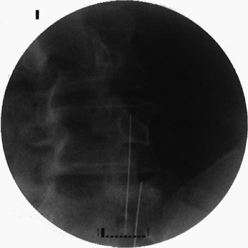 Figure 42-27. Lumbar medical branch neurotomy (prone position). Oblique view of the radiofrequency cannulae positioned parallel to the base of corresponding superior articular processes. |
Next, the AP view of the lumbar spine is obtained. The image intensifier is then rotated in the caudo-cephalad direction to the previously measured angle to achieve a sublaminar view. Insertion of the cannula parallel to the base of the SAP in the sagittal plane ensures placement analogous to that of the target nerve. The last alignment is an oblique rotation. Dynamic fluoroscopy is used to rotate the image ipsilaterally by 10 to 20 degrees until the junction of the superior proximal edge of the transverse process and the SAP is visualized (Fig. 42-30). This fluoroscopic view can be termed the “sublaminar oblique view.”
The final position at the L5 level may be different because of individual anatomic variations of iliac crest height. The image intensifier is rotated until the S1 SAP is clearly seen. The degree of obliquity depends on the extent to which the iliac crest obscures the target point. This angle will vary between 5 and 10 degrees.
When the target point is identified, skin marks are made. Local anesthetic is administered through a 25-gauge spinal needle to diminish pain from insertion of the large-bore RF cannula. Cannulae are inserted using the tunnel view technique (i.e., the target point, the tip, and the hub of the cannula should appear as a dot). The cannula, with the tip facing caudad, is inserted until contact is made with bone. The tip of the cannula is rotated cephalad and advanced a further 3 to 5 mm until bony contact is lost. The cannula is then rotated caudad and mesiad to expose the full length of the cannula tip to the target site. To confirm proper placement, lateral fluoroscopy is performed. A true lateral view is obtained when the bony landmarks are superimposed, thus eliminating the double contour appearance of vertebral bodies. In that view, the cannula tip should reach
the anterior two-thirds of the base of the SAP. This position ensures maximal contact between the active tip of the cannula and the target nerve. Deeper positioning may cause inadvertent contact with an exiting dorsal root ganglion or ventral ramus. A more posterior position means that the active tip is lying on the mamillo-accessory ligament and cannot produce a substantial lesion of the nerve (Fig. 42-31).
the anterior two-thirds of the base of the SAP. This position ensures maximal contact between the active tip of the cannula and the target nerve. Deeper positioning may cause inadvertent contact with an exiting dorsal root ganglion or ventral ramus. A more posterior position means that the active tip is lying on the mamillo-accessory ligament and cannot produce a substantial lesion of the nerve (Fig. 42-31).
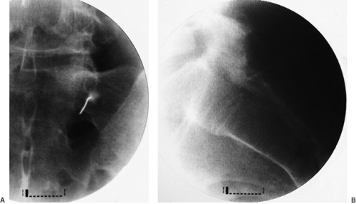 Figure 42-28. S1 dorsal ramus neurotomy (prone position). A: Anteroposterior view shows cannula at the 12 o’clock position of the superior border of the S1 posterior foramen. B: Lateral view shows cannula situated within dorsal sacral foramen. |
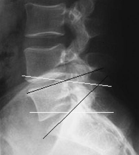 Figure 42-29. Radiographic lateral view of lumbar spine in natural vertical position. Prone positioning with a pillow usually partially eliminates lumbar lordosis. Black lines represent the sagittal plane of the superior endplate of the vertebrae. White lines are plotted through the bases of the superior articular processes. |
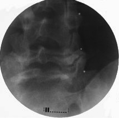 Figure 42-30. Lumbar medial branch neurotomy. Sublaminar and slightly oblique view clearly shows the junction of the superior articular processes with the corresponding transverse processes of L3, L4, and the sacral ala (white dots). |
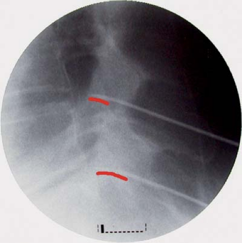 Figure 42-31. Lumbar medial branch neurotomy. Lateral view of two cannulae positioned at the base of the L5 and S1 superior articular processes. Red lines represent the medial branch of L4 and the posterior primary ramus of L5. |
If the procedure is to be successful, the lesion should be created between the posterior border of the intervertebral foramen and the mamillo-accessory ligament, where the target nerves hug the base of the SAP.
The cannula position should be confirmed in the AP view. The active tip should make contact with the bone to ensure maximal exposure to the target nerve. The cannula must be positioned snugly against the base of the SAP (Fig. 42-32).
The technique of S1 dorsal ramus lesioning is the same. The RF lesions are made as in the previously described technique.
Outcome
Numerous small studies of RF neurotomy have been done, with widely varying, but mostly positive results. The plethora of small observational studies prompted several RCTs to confirm the efficacy of the procedure, and four such studies have been published to date (19,20,21,22). Unfortunately, they all contained methodologic and technical flaws and, therefore, failed to clarify the efficacy of RF neurotomy for the treatment of zygapophysial pain. None of these studies used comparative or placebo-controlled blocks, nor did they use an anatomically validated technique (i.e., placement of the electrode parallel to the target nerve (79).
Only Dreyfuss and colleagues (78) applied strict patient selection criteria, conducted comparative double diagnostic blocks, and performed the RF procedure according to the anatomy of the target nerves. These authors also used multiple outcome tools and had a follow-up period of appropriately long duration. About 60% of the patients in their study experienced at least 90% pain relief at 12 months, and 87% experienced at least 60% relief at that time point. The only major limitation of this study was the small number of patients followed (15 patients).
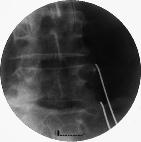 Figure 42-32. Lumbar medial branch neurotomy. Anteroposterior view of two cannulae positioned at the base of the L5 and S1 superior articular processes. |
Nevertheless, because of this work, practitioners are now called upon to use validated and anatomically correct techniques.
A large clinical audit suggested that anatomic RF denervation of lumbar zygapophysial joints provides long-term pain relief. In this study, 68.4% of patients obtained more than 50% pain relief for a median duration of 9 months (80). Notably, most patients were able to decrease their analgesic medication intake and increase physical activities.
Cryoablation of lumbar medial branches is technically feasible as well. However, the data are limited to only two prospective observational trials with questionable methodology. In the first study, patients with postlaminectomy syndrome were not excluded, and those patients (not surprisingly) obtained good (more than 50%) pain relief in 46% of cases, whereas the success rate was 85% in patients without previous surgery (81). The second study was flawed because the diagnostic protocol included only a single block. The authors reported success (pain reduction of 50% or more) in 59% of patients at 6 months’ follow-up, and in 45.6% at 12 months (82).
Sacroiliac Joint Neurotomy
The surgical anatomy of the sacroiliac joint (SIJ) innervation is not completely clear. Several anatomic studies provide differing descriptions of the various combinations of dorsal and ventral rami of the L4 to S3 branches that contribute to the SIJ nerve supply (83). A recent anatomic study, however, has
demonstrated predominant dorsal innervation of the SIJ in humans by sensory fiber types from the L5 dorsal ramus and the lateral branches of the S1–S3 dorsal rami (84) (Fig. 42-33). Thus, either RF or cryoablation of the nerves is theoretically feasible.
demonstrated predominant dorsal innervation of the SIJ in humans by sensory fiber types from the L5 dorsal ramus and the lateral branches of the S1–S3 dorsal rami (84) (Fig. 42-33). Thus, either RF or cryoablation of the nerves is theoretically feasible.
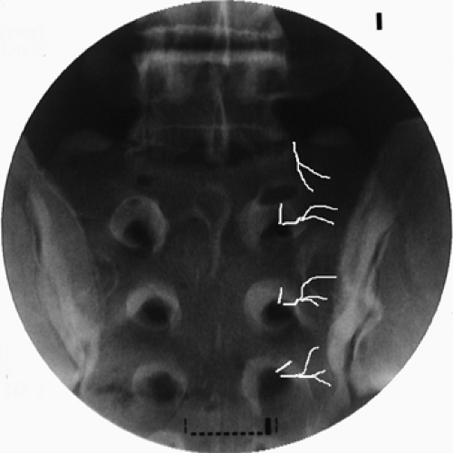 Figure 42-33. Lumbo-sacral lateral branch neurotomy (prone position). L5–S3 lateral branches topographic fluoroscopic anatomy (white lines). |
The diagnosis of SIJ pain must be confirmed by diagnostic blockade. However, comparative block has not been validated in the context of intra-articular injections. Because the duration of action of local anesthetics is not well defined when they are administered into a joint, a method of anatomical control has been proposed (85). A positive response to the SIJ block is more compelling if the patient had a negative response to the zygapophysial nerve block and/or to lumbar provocation discography. The fact that the patient has not exhibited a placebo response following previous injection might increase the credibility of the response to the SIJ block.
As for RF or cryoablation of SIJ nerves, both procedures share the inconsistencies published for the nerve supply and diagnostic algorithm. The technique of cryoablation has been briefly outlined without data on outcome (40). Two essentially different techniques of RF treatment have been described. The first, called nonstimulation-guided bipolar RF lesioning along the posterior joint line, has yielded mediocre results, with only 36.4% of patients having obtained more than 50% pain relief for more than 6 months (86). The second method, selective lesioning of symptomatic lateral branches, is more theoretically attractive. Using this method, 64% of patients reported more than 50% pain relief, and 36% were pain-free after 6 months of follow-up (87). In another study, Cohen and Abdi evaluated RF lesioning of the L4 medial branch, the L5 dorsal ramus, and lateral branches of S1 to S3 in nine patients, reporting that 89% obtained more than 50% pain relief from this procedure that persisted at the 9-month follow-up (88).
Unfortunately, both studies were retrospective and small, consisting of 14 and nine patients, respectively. Furthermore, radiograms of the procedure are not convincing enough to conclude that cannulae were placed parallel to the nerves. Therefore, the current level of evidence for RF neurotomy in the treatment of SIJ pain should be considered as indeterminate.
Technique
A curved 100-mm, 20-gauge RF cannula with a 10-mm active tip is suitable for this procedure. Under fluoroscopic imaging, the cannula is placed at the base of the S1 SAP, as described earlier, to perform the lesion of the L5 dorsal ramus. Separately, the RF cannulae are directed to the lateral edge of the dorsal sacral foraminal apertures of S1 to S3 (sacral dorsal rami lateral branch nerves). At each location, 50-Hz, 1-ms stimulation is applied at 0.4 to 0.7 V (“searching” voltage). The RF cannulae are finely manipulated under fluoroscopic imaging around the target structures until either a reproduction of concordant/usual pain or paresthetic cutaneous sensation is elicited. Stimulation has to be performed through the 2 o’clock to 6 o’clock zone on the right or the 6 o’clock to 10 o’clock zone on the left (if the dorsal sacral foramen is viewed as a clock face). Stimulation voltage must be as low as 0.1 to 0.2 V to ensure the contact with the target nerve. Absolutely consistent and reproducible elicitation of specific and concordant pain is interpreted as successful localization of the symptomatic lateral branch, whereas the elicitation of cutaneous paresthesiae without pain is interpreted as localization of asymptomatic nerves.
Related posts:


Stay updated, free articles. Join our Telegram channel

Full access? Get Clinical Tree


