Key Clinical Questions
What are the components of an implantable pacing or defibrillation system?
How do pacemakers interact with the heart’s natural rhythm to know when to and when not to pace?
What do the common pacing codes (ie, VVI, DDD) mean, and how do they affect the electrocardiogram (ECG)?
When should patients be referred for cardiac resynchronization therapy (CRT)?
How should clinicians evaluate the patient who has received an implantable cardiac defibrillator (ICD) shock?
When should a pacemaker or ICD be interrogated in the inpatient setting?
Introduction
Advances in technology and the expansion of indications have greatly increased the number of patients receiving pacemakers and implantable cardiac defibrillators (ICDs). Approximately 200,000 pacemakers and 100,000 defibrillators are implanted annually for the management of cardiac arrhythmias, treatment of congestive heart failure, and the prevention of sudden cardiac death. These devices have progressed from relatively simple components with basic pacing and defibrillation features, to more advanced systems with a significant impact on patient morbidity and mortality. The increasing number and complexity of devices encountered in hospitalized patients frequently presents a clinical management challenge. The purpose of this chapter is to introduce basic concepts of pacing and defibrillation, review standard indications for cardiac rhythm devices, and highlight pertinent clinical considerations for hospitalist care of patients with these devices.
Equipment and Hardware
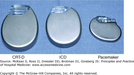
Cardiac pacing and defibrillating systems consist of pulse generators and leads. The pulse generator is the “device” that contains the battery, circuitry, and capacitors. It is typically encased in a titanium housing that ranges in size and shape depending on the manufacturer. Defibrillator pulse generators are about two to three times larger than pacemakers (Figure 129-1).
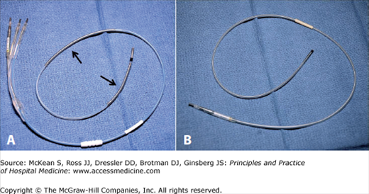
The leads are connected to the pulse generator at the time of implant and are attached distally to the myocardium. They are secured to the myocardium either “actively” by means of a small screw, or “passively” by means of small tines near the lead tip. Pacemaker leads consist of conducting wires, a silicone or polyurethane insulation coating, and platinum electrodes used for pacing. Defibrillation leads have one or two additional wire coils capable of delivering high-voltage impulses for defibrillation (Figure 129-2).
Technologic advancements in the field of cardiac rhythm devices have resulted in smaller batteries with increased life spans. Most batteries used in modern devices are lithium-based and are nonrechargeable with a finite life span. Typically, a pacemaker battery will last approximately 10 years, while an ICD battery will last approximately five years. Once exhausted, these batteries must be exchanged.
|
Battery longevity depends on several factors, the most important of which include pacing output, the relative amount of time pacing is required, and the number of programmable features that are activated on the device. Furthermore, frequent ICD therapies represent a common cause for battery drain. The cardiologist managing the patient will tailor device programming to maximize battery life without sacrificing the clinical function of the device.
The remaining life of a battery is displayed each time the device is interrogated. As battery life declines, the device will enter a period called elective replacement interval (ERI). This alerts the physician that there are approximately two to three months of remaining battery life and the patient should be scheduled for elective replacement of the device. Further depletion of the battery will lead to the end-of-life (EOL) period, an indication that the battery should be replaced as soon as possible. Importantly, as batteries enter the ERI and EOL periods, certain features of the device will automatically turn off to preserve as much battery life as possible. This may result in a reduction in the clinical benefit a patient receives from the device.
Basic Pacing Concepts
The two primary functions of pacemakers are sensing and pacing. Sensing refers to the ability of the device to detect native impulses originating from the heart. These sensed events are used to time subsequent events based on programmable settings. The ability of the device to sense a native impulse depends on the amplitude of the electrical signal generated by the heart, as seen by the device. Undersensing occurs when the amplitude of the signal is insufficient for detection by the pacemaker and results in inappropriate pacing by the device (Figure 129-3). Oversensing occurs when the device inappropriately interprets signals as native impulses. Oversensing leads to inappropriate inhibition of pacing, and may occur as a result of internal or external “noise” detected by the device (Figure 129-4). When oversensing occurs in an ICD, the device can misinterpret the signals as a ventricular arrhythmia and inappropriately shock the patient.
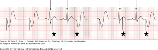
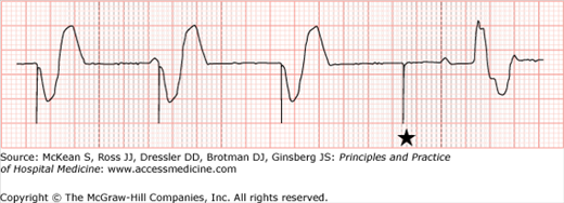
Figure 129-4
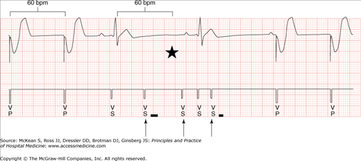
Ventricular oversensing. This device is programmed VVI with a lower rate limit of 60 bpm. The markers noted by arrows show where ventricular oversensing occurs (VS). This causes an inhibition of pacing. Had oversensing not occurred, pacing would have occurred at the point marked by the star.
|
Pacing output is the electrical stimulation that results in myocardial depolarization and contraction of the heart. The minimal amount of electrical energy required to cause depolarization is termed the capture threshold, and it is a function of the electrode-tissue interface. Pacing output is programmed sufficiently above the capture threshold to provide an adequate safety margin. This output is seen on surface electrocardiograms as a discrete “spike” called a pacing stimulus artifact. Importantly, modern devices with bipolar pacing and low energy outputs can generate a relatively small stimulus artifact that may be difficult to see on surface tracings. Careful attention to the tracing will usually reveal these small artifacts.
When insufficient energy is delivered by the device, the electrical stimulus may fail to depolarize the myocardium. This is called failure to capture. It is recognized when a pacing stimulus artifact is not followed by a P wave or QRS complex (depending on which chamber is being paced), and occurs as a result of either inappropriately low output or poor electrode-tissue interface from lead dislodgement. Failure to capture is relatively uncommon in chronic devices with stable leads. When failure to capture occurs in patients who are pacemaker dependent, dangerously low heart rates may result (Figure 129-5).
|
There are multiple programmable intervals pacemakers use to determine when to deliver pacing output. The most important of these include lower rate limit, AV interval, and upper rate limit (Figure 129-6). The lower rate limit is the slowest rate that a pacemaker will allow the heart to reach. When the heart rate drops below this rate, the pacemaker will begin pacing. However, as long as the heart rate exceeds this rate, pacing will not occur. Therefore, lack of pacing on a surface ECG in this instance does not indicate device malfunction.
Figure 129-6
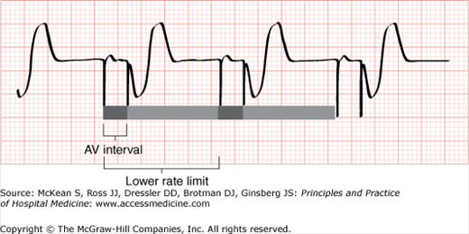
Schematic demonstrating the concepts of lower rate limit and AV interval. This device is programmed DDD. An atrial event is not sensed before the lower rate limit expires, so atrial pacing occurs at the programmed rate. Native AV conduction does not occur within the programmed AV interval, so ventricular pacing occurs. See text for details.
|
The AV (atrioventricular) interval is the time allowed after an atrial event before ventricular pacing will occur. This is analogous to the PR interval. As long as native AV conduction occurs within this interval, ventricular pacing will be inhibited. However, if the AV interval expires before native AV conduction occurs, then ventricular pacing will occur.
The AV interval is typically programmed sufficiently long to promote native conduction, as chronic right ventricular pacing increases morbidity in certain patient populations. The most important exception to this is in the case of cardiac resynchronization in patients with biventricular pacemakers. In this situation, the AV interval is programmed relatively short, to provide the physiologic benefits of biventricular resynchronization.
The upper rate limit is a programmed rate above which the pacemaker will not pace. In patients with sinus or atrial tachycardia that exceeds the upper rate limit, the pacemaker will pace the ventricle only as fast as the upper rate limit. This may result in atrial events that are not followed by ventricular pacing, and may lead to misinterpreting pacemaker function from the surface electrogram.
Most surface electrograms in patients with pacemakers can be explained by these basic pacing functions. However, there are an increasing number of programmable features in modern devices designed to enhance overall pacing function. These features may mimic device malfunction in the form of oversensing, undersensing, or other strange phenomena, and may require the assistance of a cardiologist to interpret. While true device malfunction does occur, it is relatively uncommon. Apparent malfunction based on surface electrograms can usually be explained by normal device function.
One common source of confusion is interpretation of the nomenclature used to describe pacemaker function. The current system in use was revised in 2002 by the North American Society of Pacing and Electrophysiology (NASPE) and uses a letter system to describe pacemaker function (Table 129-1). The first and second letters are used to identify the chamber(s) in which there is pacing and sensing, respectively. The third letter indicates the effect of sensing on subsequent pacing stimuli. Sensed events can induce (trigger) pacing, inhibit pacing, or both.
Related posts:
 Strategies for Cost-Effective Care
 Building, Growing, and Managing a Hospitalist Practice
 Designing a Hospitalist Compensation and Bonus Plan
The Face of Health Care Emerging Issues for Hospitalists
Designing a Hospitalist Compensation and Bonus Plan
The Face of Health Care Emerging Issues for Hospitalists
 Medical Malpractice
Preventing and Managing Adverse Patient Events: Patient Safety and the Hospitalist
Medical Malpractice
Preventing and Managing Adverse Patient Events: Patient Safety and the Hospitalist
Stay updated, free articles. Join our Telegram channel

Full access? Get Clinical Tree


