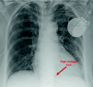
Fig. 10.1
Dual-chamber pacemaker

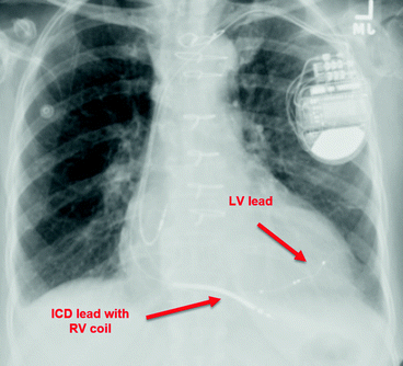
Fig. 10.2
Single-chamber ICD

Fig. 10.3
CRT-D
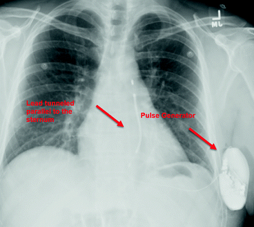
A transvenous CIED will generally have a pulse generator located in the prepectoral region. An epicardial system may have an abdominal pulse generator. Alternatively, the leads may be tunneled to the right or left prepectoral region. A subcutaneous ICD will have a distinct radiographic appearance (Fig. 10.4). The generator is implanted at the mid-axillary line at the 5th to 6th intercostal space and the lead is tunneled such that it runs parallel to the sternum.


Fig. 10.4
Subcutaneous ICD
- 2.
What are the components of a cardiac implantable electrical device?
All pacemakers are composed of two components: the pulse generator and the lead(s). The pulse generator is responsible for generating the electrical impulse that depolarizes the myocardium resulting in contraction of a cardiac chamber. Two types of lead systems exist: unipolar and bipolar. In a unipolar system, the lead in contact with the endocardium is the cathode and the pulse generator is the anode. In a bipolar lead, the lead tip is the cathode and the lead ring is the anode. Voltage in a unipolar lead is detected over a larger distance and as such, the pacing spike on an electrocardiogram is larger than with a bipolar lead. Types of leads include active fixation leads which are screwed into the myocardium and passive fixation which are held in place with fins.
The implantable cardioverter defibrillator (ICD) has two main components: the pulse generator and the leads. The pulse generator itself consists of a battery, a capacitor which facilitates charging and discharging, and circuits to monitor, analyze, and guide arrhythmia therapies. Cardioversion or defibrillation is delivered via a biphasic waveform between the shocking coil and the ICD pulse generator and then the reverse.
- 3.
Describe the code used to describe the function of pacing devices.
The North American Society of Pacing and Electrophysiology and the British Pacing and Electrophysiology Group (NASPE/BPEG) created the five position NBG pacemaker code to describe pacemaker functions (see Table 10.1).
Table 10.1
The revised NASPE/BPEG generic code for antibradycardia pacing
Position I chamber(s) paced | Position II chamber(s) sensed | Position III response to sensing | Position IV rate modulation | Position V multisite pacing |
|---|---|---|---|---|
O = None | O = None | O = None | O = None | O = None |
A = Atrium | A = Atrium | T = Triggered | R = Rate modulation | A = Atrium |
V = Ventricle | V = Ventricle | I = Inhibited | V = Ventricle | |
D = Dual (A + V) | D = Dual (A + V) | D = Dual (T + I) | D = Dual (A + V) | |
Sa = Single (A or V) | Sa = Single (A or V) |
Position I indicates the chamber (or chambers) paced. A device used to pace in only one chamber will be represented by either the letter A (atrial) or V (ventricle). Devices that can pace in both chambers are represented by the letter D (dual). When pacing is off, position I coding is O (off).
Position II represents the chamber sensed for intrinsic signals. The letters are the same as those for the first position with A (atrium), V (ventricle), and D (dual). An O in position II indicates the absence of sensing. Programmed in this mode, the device will pace asynchronously at a specified rate, ignoring any intrinsic rhythm.
Position III represents the response to a sensed event. “I” indicates that a sensed event inhibits the output pulse. “T” indicates that an output pulse is triggered in response to a sensed event. D indicates that there are dual modes of response. This is restricted to dual-chamber systems. For example, an event sensed in the atrium inhibits atrial output but triggers ventricular output. If the ventricular lead senses an intrinsic ventricular signal during the programmed delay, it will inhibit ventricular output. O indicates no response to a sensed input.
Position IV reflects rate modulation, which is also known as rate responsiveness. R indicates that the pacemaker has rate modulation and will use sensor data to adjust its programmed paced heart rate in response to patient activity. O indicates that rate modulation is either unavailable or disabled. O is often omitted from the fourth position (i.e., DDD is the same as DDDO).
Position V indicates whether multisite pacing is present in (O) none of the cardiac chambers, one or both atria (A), in one or both ventricles (V) or (D) any combination of A or V. Multisite pacing may also refer to more than one stimulation site in a particular chamber. The fifth position of the code is rarely reported.
Stay updated, free articles. Join our Telegram channel

Full access? Get Clinical Tree


