Fig. 20.1
Infraclavicular incision with self-retaining retractor for exposure
Venous Access
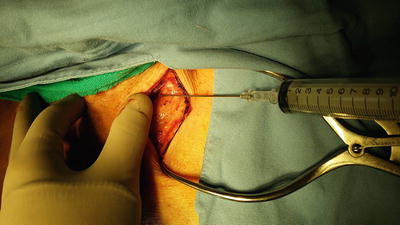
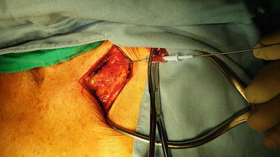
The patient is placed in a slight Trendelenburg position and using the modified Seldinger technique, the subclavian vein, which is the preferred route, may be accessed (Figs. 20.2 and 20.3). Alternatively, the venous access may be obtained via an internal jugular approach or even a venous cutdown onto the cephalic vein in the deltopectoral groove. Once the guidewire is inserted into the vein, fluoroscopy is used to confirm proper positioning of the guidewire in the area of the superior vena cava–right atrial junction.


Fig. 20.2
Subclavian vein puncture

Fig. 20.3
Insertion of guidewire using Seldinger technique
Lead Placement
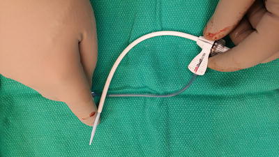
If the patient is not in chronic atrial fibrillation, then typically, a dual chamber pacemaker utilizing an atrial and ventricular lead is preferred. This allows for a more physiologic stroke volume by providing the additional atrial volume or “atrial kick” that sequential pacing of the atrial and ventricular chambers provides. The ventricular lead introducer and sheath is curved in order to facilitate easier passage toward the right atrial–superior vena cava junction (Fig. 20.4). The introducer and sheath are passed over the guidewire and then while leaving the guidewire in place, the introducer is removed leaving the sheath in place (Fig. 20.5). The ventricular lead, which is an insulated conducting wire, is then inserted into the sheath (Fig. 20.6) and the Teflon-coated “split” sheath catheter is then removed. The lead has an inner guidewire which is curved in a “pigtail” or “hockey stick” configuration in order to be able to manipulate the lead into the ventricular chamber and assist in optimal positioning of the lead (Fig. 20.7). Under fluoroscopic guidance, the ventricular lead is passed into the atrium through the tricuspid valve and then passed toward the pulmonary outflow tract (Fig. 20.8). The curved guidewire is replaced with a straight guidewire and then under fluoroscopy, the ventricular lead is pulled back into the right ventricle and then directed toward the right ventricular apex. When properly positioned, the ventricular lead has a slightly angled appearance aimed inferiorly and laterally toward the apex of the heart (Fig. 20.9). Once placed, the pacemaker lead is interrogated by attaching the alligator-clipped cables onto the end of the lead in order to obtain and confirm adequate electrophysiologic parameters (Fig. 20.10). This is usually provided with the assistance of the pacemaker technician. Upon obtaining satisfactory cardiac parameters, the ventricular lead is secured in place and the atrial lead (if indicated) is inserted. The atrial introducer and sheath is inserted over the guidewire, which up to this point has been left in the subclavian vein. The guidewire is then removed leaving the introducer–sheath in place because typically the atrial introducer does not have a large enough bore to accommodate both the atrial lead and the guidewire, as was the case with the ventricular lead (Fig. 20.11). The atrial lead, with its guidewire, is inserted into the split sheath introducer. The introducer is removed leaving the lead in place. While visualizing under fluoroscopy, and while insuring that the ventricular lead is not dislodged, the atrial lead is inserted into the region of the right atrium–superior vena cava junction. The atrial lead’s guidewire is partially withdrawn to allow the atrial lead to insinuate itself into the right atrial appendage (Fig. 20.12). Most atrial leads have a manufactured J-shaped configuration to allow for easier placement (Fig. 20.13). Once proper position is obtained, interrogation using the pacemaker cables is performed to confirm that the atrial lead placement is optimal. Upon completion of the lead placement, the guidewires are removed completely from their respective leads and the leads are sutured to the pectoralis muscle fascia using 2-0 Surgidac/Ti-cron (Fig. 20.14).


