The evaluation of valvular heart disease has become increasingly dependent on echocardiography. Since its introduction to the operating room, transesophageal echocardiography (TEE) has played a major role in surgical decision making and anesthetic management of patients undergoing mitral valve surgery. Mitral valve replacement has its own implications and is not free of risk, leading surgeons to develop techniques for mitral valve repair, which are becoming more and more intricate as our understanding of valve function expands. Recent outcome literature indicates strong support for repair relative to replacement in patients with organic, nonischemic mitral valve pathology,1 and the role of intraoperative TEE in mitral valve repair2 and replacement surgery3 is well established. A good knowledge of mitral valve anatomy and its assessment by TEE is therefore vital to any successful intraoperative echocardiographer.
The mitral valve is located between the left atrium and the left ventricle and allows unidirectional flow of blood towards the left ventricle, prevents backward flow of blood into the left atrium during left ventricular systole, and allows unobstructed flow of blood to the left ventricle during diastole, maintaining low left atrial pressures. The anterior mitral valve leaflet also forms part of the left ventricular outflow tract and allows for unimpeded left ventricular ejection during systole. For the mitral valve to function normally, it relies on the integrated function of a number of structures, which are collectively referred to as the mitral valvar complex. This complex consists of the anterior (aortic) and posterior (mural) leaflets, together with the annulus, chordae tendineae, papillary muscles, and left ventricle. Abnormalities of any of these structures can result in valvular dysfunction, and should therefore be included in the comprehensive evaluation of the mitral valve.4
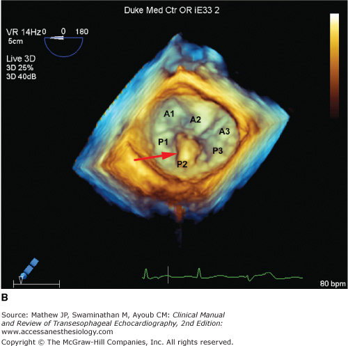
Two leaflets separated by two commissural areas cover the mitral valve area during systole. The anterior or aortic leaflet is situated anteriorly and to the right, adjacent to and in continuum with the aortic valve, and occupies approximately one-third of the annular circumference. Both the aortic and mitral valves contribute to the so-called fibrous skeleton of the heart, and the connection between the two is sometimes described as the aortomitral continuity. The posterior or mural leaflet occupies the remaining two-thirds of the annular circumference and is much narrower than the anterior leaflet. Although the posterior leaflet appears to have less height than the anterior leaflet, they are similar in surface area. The posterior leaflet is subdivided into three scallops by clefts. The scallop adjacent the anterolateral commissure is named P1, with P3 situated on the other end of the posterior leaflet in close relation to the posteromedial commissure. P2 is the middle scallop in between P1 and P3. Even though the anterior leaflet is not anatomically divided into scallops, the areas opposing the posterior leaflet are correspondingly referred to as the A1, A2, and A3 segments (Figure 7–1).5 Closure of the valve requires apposition and coaptation of the two leaflets, and this occurs along a single semilunar coaptation line. The ends of this coaptation line do not extend all the way to the annulus and are known as commissures. These commissural areas are situated anterolaterally and posteromedially, in relation to their papillary muscles.
Figure 7-1.

This full-volume 3D dataset of the heart demonstrates the mitral valve during diastole. The anterior leaflet, scallops of the posterior leaflet (P1, P2, P3), and both anterolateral and posteromedial commissures are clearly visible. (AOV, aortic valve; LAA, left atrial appendage; ALC, anterolateral commissure; PMC, posteromedial commissure; AML, anterior mitral leaflet.)
Anatomically, the annulus is formed by lateral extensions of fibroelastic tissue, originating from the left and right fibrous trigones. The amount of fibrous tissue decreases towards the inferolateral aspect of the annulus until only myocardium is present, making the inferolateral annulus most susceptible to dilatation. The aortomitral fibrous continuity, another area where the annulus is not well defined, is situated between the two trigones. Left atrial implantation serves as an indicator of the mitral annulus in this region. Undulations in the mitral annulus results in a saddle shape, with the commissural areas located more towards the ventricle and the intertrigonal and posterolateral areas located more towards the left atrium. The annulus is oval shaped, with the intercommissural (intertrough) distance greater than the aortic to mural (interpeak) distance. The valve is slightly tilted in the chest, with the anterior part superior to the more inferiorly positioned inferolateral part.
The subvalvular apparatus consists of two papillary muscles supporting the mitral valve leaflets by means of multiple chordae tendineae. The posteromedial papillary muscle is found in close relation to the posteromedial commissure and the interventricular septum. In the case of the mitral valve, there is no direct leaflet connection to the interventricular septum as occurs with the tricuspid valve septal leaflet. This is a distinguishing feature allowing identification of the tricuspid or mitral valve where transposition is suspected. Blood supply to the posteromedial papillary muscle is usually provided by a single coronary artery. Depending on dominance of the circulation, it can be either a branch from the posterior descending artery, or a branch from the obtuse marginal artery. The anterolateral papillary muscle is found in relation to the anterolateral commissure and receives blood supply from both the left anterior descending artery via the first marginal artery, and from the circumflex artery via the first obtuse marginal artery. This dual supply makes dysfunction of the anterolateral papillary muscle less likely.6
Primary chordae tendineae stretch from the papillary muscles and attach to the tips of the mitral valve leaflets. Secondary and tertiary chordae also attach to the body and base of the leaflets, respectively. Separate chordae also originate from the left ventricular free wall and attach to the ventricular surface of the posterior leaflet, in particular. During ventricular systole, contraction of the papillary muscles and left ventricular free wall therefore prevents the mitral valve leaflets from prolapsing into the left atrium. Dysfunction of the papillary muscles or chordae can cause mitral valve dysfunction by either allowing excessive motion of the leaflets or by restricting movement of the leaflets and thus preventing proper coaptation.
The left ventricular myocardium determines the position of the papillary muscles relative to the mitral coaptation point. Left ventricular dilatation alters the spatial relation of the papillary muscles and attachment of tertiary chordae to the leaflets, thus moving the coaptation point deeper into the ventricle. The result is tethering of the leaflets with inadequate coaptation and valvular dysfunction.
The role of the left atrium in normal mitral valve function is not clearly defined. However, left atrial tissue is continuous with the mural leaflet and may potentially interfere with normal leaflet motion when left atrial dilatation occurs.7 The atrial attachment to the aortomitral fibrous continuity is also the hinge point of the aortic leaflet, and atrial dilatation may therefore affect the function of the aortic leaflet.
Complete and accurate two-dimensional (2D) echocardiographic assessment of mitral valve morphology requires the examiner to obtain multiple tomographic two-dimensional views and mentally reconstruct a three-dimensional interpretation (Figure 7–2). Three-dimensional imaging, when it is available on all ultrasound systems, will make such mental reconstruction unnecessary (Figure 7–3). The following views, included in the American Society of Echocardiography (ASE)/Society of Cardiovascular Anesthesiologists (SCA) guidelines for performing a comprehensive intraoperative TEE exam, allow systematic assessment of the mitral valve.8


This view is achieved by gently retroflexing the probe in the midesophageal position, directing the imaging sector towards the cardiac apex through the mitral valve. In the classical ME 4 CH view, which is obtained at 20° to 30°, the imaging plane transects the mitral valve in an oblique plane relative to the valve commissures, thus showing the A3 segment of the aortic leaflet to the left of the display and the P1 scallop of the posterior leaflet to the right of the display (see Figures 7–2 and 7–3). By withdrawing or anteflexing the probe slightly, the tomographic plane will transect the valve closer to the anterolateral commissure, bringing the left ventricular outflow tract (LVOT) into view, while advancing or retroflexing the probe slightly transects the valve more toward the posteromedial commissure. When the ME 4 CH imaging plane is at 0° (often the five-chamber rather than four-chamber view), the middle part of the aortic leaflet (A2 segment) and the more anterior part of P2 are seen. Any subvalvular or LVOT pathology can be visualized in this view.
From the ME 4 CH view, the multiplane angle of the probe is electronically rotated forward to approximately 60°, aligning the tomographic sector with the mitral valvar commissures. In this view, the P1 scallop is viewed to the right of the screen, and the P3 scallop to the left of the image. In the middle will be the A2 segment moving in and out of view as the valve opens and closes (see Figures 7–2 and 7–3). P2 will be behind A2 (into the screen), but is usually not visible unless it is prolapsing. Applying color Doppler imaging to the valve and rotating the probe in small increments allows one to accurately identify the origin of any mitral regurgitation jet.
Further rotation of the multiplane angle to approximately 90° displays this view. Once again, the imaging sector cuts through the mitral valve at an oblique angle relative to the commissures, showing the more anterior parts of the aortic leaflet (A2, A1) to the right of the image and the more posterior parts of the mural leaflet (P3) to the left of the image (see Figures 7–2 and 7–3).
With the multiplane angle between 120° and 140°, the aortic valve should appear in its long axis together with the mitral valve. This imaging plane cuts through the mitral valve perpendicular to the coaptation line, and in diastole clearly demonstrates the aortomitral continuity and the unfolded length/height of A2, together with P2 (see Figures 7–2 and 7–3). Turning the probe to the right will show the more posterior part of the mitral valve (A3/P3), and leftwards the more anterior parts of the mitral valve (A1/P1). Since the midesophageal long-axis view intersects the mitral valve perpendicular to the coaptation line, it is the best view to measure the interpeak distance of the annulus (Figure 7–4) or the diameter of a mitral regurgitant jet vena contracta in systole (Figure 7–5). The left ventricular outflow tract is also clearly visualized to assess any subaortic valve or outflow tract pathology.


Advancing the probe into the stomach and rotating the multiplane angle forward to approximately 90° demonstrates this view (Figure 7–6). Here, the subvalvar apparatus can be assessed, with the posteromedial papillary muscle in the near field and the anterolateral papillary muscle in the far field. Chordal pathology can also be identified and located.
Figure 7-6.

In the transgastric two-chamber view, the subvalvular apparatus can be readily assessed. In this view, the chordae (arrows) are easily seen, and the posteromedial papillary muscle is seen in the near field while the anterolateral papillary muscle is seen in the far field. (LA, left atrium; LV, left ventricle.)
From the transgastric two-chamber view, the probe is slowly withdrawn until the mitral valve is in the middle of the image and perpendicular to the tip of the probe. The multiplane angle is reduced to 0°, and the mitral valve will now be seen in short axis. The anterolateral commissure together with A1/P1 will be in the far field and to the right of the image, while the posteromedial commissure and A3/P3 are in the near field and to the left of the image (Figure 7–7). Although quantification of mitral valve pathology with color Doppler is not possible in this view, it is helpful to identify the origin of mitral regurgitation. One should be careful not to confuse the color jet of aortic regurgitation with a color jet originating from mitral regurgitation.
Figure 7-7.

In the transgastric basal short-axis view (A), the mitral valve is seen with the anterolateral commissure (ALC) in the far field and to the right of the image, while the posteromedial commissure (PMC) is in the near field and to the left of the image. In this patient with a dilated cardiomyopathy, the ventricle is more spherical and a central mitral regurgitant jet (arrow) is identified with color Doppler (B). (AML, anterior mitral leaflet; PML, posterior mitral leaflet.)
It is important to complete a 2D evaluation of the mitral valve before color Doppler is applied in order to establish mechanisms of mitral valve disease as well as its hemodynamic consequences. Chamber enlargement and indirect signs of pulmonary hypertension are indicators of severe degrees of mitral valve disease, as well as long-standing pathology.
After a comprehensive 2D examination of the valve, color Doppler is applied to all of the midesophageal views. In order to achieve good temporal resolution, it is necessary to keep the two-dimensional and color Doppler sectors as small as possible, but still big enough to include the whole mitral valve area of interrogation. A frame rate of at least 15 frames per second is considered adequate. With color Doppler the presence of mitral regurgitation (in systole) or mitral stenosis (in diastole) can be demonstrated. Pulsed-wave and continuous-wave Doppler should be applied across the valve to quantify the degree of mitral valve disease severity, and will be discussed below under specific headings.
Considerable experience is usually required to mentally integrate a number of two-dimensional views of the mitral valve into a three-dimensional structure and then present a clear description to the surgeon. The recent introduction of real-time three-dimensional (3D) transesophageal echocardiography into clinical practice is proving to add incremental value in localizing and demonstrating mitral valve pathology during repair procedures.9,10 The spatial and temporal resolution of the currently available matrix array transesophageal transducer allows three-dimensional views of unparalleled quality at acceptable frame rates (see Figure 7–3). A single 3D volume acquisition allows a comprehensive 2D evaluation in any plane extracted from the dataset. It significantly reduces the number of steps required to complete a comprehensive examination of the mitral valve, thus reducing the examination time.11 The feasibility of intraoperative geometric analysis using integrated 3D mitral valve assessment software has been confirmed, providing much greater quantitative assessment of the mitral valve within the operative environment than has ever been possible.12 Postoperatively, it also provides excellent views of both bioprosthetic and mechanical valves and annuloplasty rings or bands (see Chapter 24).13 It is expected that a combined 2D and 3D transesophageal echocardiography examination will in the foreseeable future become routine for preoperative surgical planning and guidance during mitral valve procedures.
Mitral valve prolapse (MVP) is characterized by the displacement of an abnormally thickened mitral valve leaflet into the left atrium during systole. Thickening of the mitral leaflets greater than 5 mm and leaflet displacement greater than 2 mm indicates classic MVP. In severe cases of classic MVP, complications include mitral regurgitation, infective endocarditis, congestive heart failure, and in rare circumstances, cardiac arrest, usually resulting in sudden death. Early studies estimated a prevalence of 38% among healthy teenaged males, but with improved echocardiographic techniques and clear diagnostic criteria, the true prevalence of MVP is estimated at 2% to 3% of the population.14
Mitral regurgitation results from the incomplete closure of the mitral valve leaflets during left ventricular systole, resulting in backflow of blood into the left atrium. The amount of backflow will determine the hemodynamic consequences of the mitral regurgitation and appears to be mostly affected by the area of the regurgitant orifice. Other factors that influence the amount of regurgitation include the duration of systole and the pressure gradient between the left ventricle and atrium.
Normal size and function of the left atrium, left ventricle, mitral annulus, and leaflets is required to ensure a competent mitral valve complex. Dysfunction of any of these components can result in mitral regurgitation. Typically, leaflet motion will be altered in a way to prevent adequate coaptation and apposition. A functional classification of mitral regurgitation was proposed by Carpentier in the 1980s,15 whereby valvular pathology is described in terms of the opening and closing motion of the leaflet (Figure 7–8). This allows a better understanding of the etiology and type of valvular dysfunction. In mitral valve repair, this classification also helps in deciding whether repair is feasible or not and which type of surgical procedure will be best suited for the specific lesion.

Type I lesions are characterized by normal leaflet motion, and mitral regurgitation is caused by annular dilatation or leaflet perforation. The resultant mitral regurgitation jet is usually centrally directed (Figure 7–9A).
Type II lesions result from increased leaflet motion. This results from elongated or ruptured chordae allowing the affected leaflet to move beyond the coaptation point and level of the annulus. The direction of the mitral regurgitation jet is directed away from the pathological leaflet (Figure 7–9B).
Type III lesions are the result of restricted leaflet motion. This category is differentiated into type IIIa and type IIIb lesions. In type IIIa lesions, leaflet motion is restricted during systole and diastole and is usually the consequence of rheumatic heart disease. This type of mitral regurgitation is seldom seen in isolation as the diastolic restriction causes varying degrees of stenosis as well. The usually eccentric mitral regurgitation jet is more likely to be in the direction of the pathological restricted leaflet (Figure 7–9C). When both leaflets are equally involved in the disease process, the jet may be centrally directed. In type IIIb lesions, leaflet motion is restricted during systole and is the result of displacement of either one or both of the papillary muscles, or any segment of the ventricular wall, as found in ischemic mitral regurgitation. The posterior leaflet is typically involved, and the regurgitant jet is directed towards the restricted leaflet. It can also be due to a global ventricular dysfunction as found in dilated cardiomyopathy. In this condition both leaflets are tethered and pulled out of position by the chordae and dilated ventricle, leading to tenting and poor coaptation, with the coaptation point displaced into the ventricle (Figure 7–9D). A type IIIb lesion is a ventricular problem and the leaflets themselves are not abnormal. Type IIIb is also usually accompanied by a dilated annulus.
Figure 7-9.

A: Carpentier type I: This midesophageal long-axis view demonstrates a central jet of functional MR because of a high ventricular pressure and annular dilatation, due to concurrent aortic valve stenosis. The MV is morphologically normal. B: Carpentier type II: The color Doppler study demonstrates the eccentric incompetence jet directed away from the pathological anterior leaflet in a posterolateral direction. C: Carpentier type IIIa: This patient has rheumatic heart disease with movement of the posterior leaflet restricted during systole and diastole. The eccentric regurgitant jet is directed towards the pathological posterior leaflet. D: Carpentier type IIIb: This midesophageal four-chamber view demonstrates restricted MV leaflet motion as found with global ventricular dysfunction. Both leaflets are pulled out of position by the chordae and dilated ventricle, leading to tenting and poor coaptation, with a central MR jet.
Rheumatic heart disease results in thickening and deformation of the mitral leaflets (Figure 7–10) with subsequent insufficient coaptation (almost always associated with mitral stenosis). Infective endocarditis can result in direct destruction of valvar tissue, preventing closure, or even perforation, of the leaflets. Furthermore, the presence of large vegetations can also interfere with proper closure of the valve.

The intercommissural annular dimension (intertrough distance) is greater than the dimension measured perpendicular to the mitral coaptation surface (interpeak distance), resulting in an oval-shaped mitral annulus. Furthermore, the inferolateral mitral annulus is almost devoid of fibrous support and is the area most likely to be involved in annular dilatation. Thus, when annular dilatation occurs, the ratio of interpeak to intertrough distance is altered. The result is an inability of the mitral leaflets to coapt sufficiently to prevent the backflow of blood to the left atrium during systole.
Annular calcification can also result in improper leaflet motion and subsequent mitral regurgitation. Degenerative calcification is accelerated by conditions such as systemic hypertension, aortic stenosis, and diabetes. Intrinsic abnormalities of the fibrous skeleton of the heart, such as is found in patients with Marfan and Hurler syndromes, as well as other connective tissue diseases, may result in accelerated calcification as well as annular dilatation. Patients with hyperparathyroidism secondary to renal disease may suffer from early calcification of the mitral annulus. Annular calcification can also result in mitral stenosis, and mixed valvular disease is common.
The presence of mitral regurgitation of hemodynamic significance results in a volume overload of the left ventricle with subsequent dilatation. During systole this ventricle offloads into the left atrium and therefore experiences a falsely low afterload, resulting in apparent hyperdynamic ventricular function. Ventricular dilatation is often accompanied by mitral annular dilatation, which is a compounding factor in other mechanisms of mitral regurgitation.16 For this reason one will often hear that “mitral valve regurgitation begets mitral valve regurgitation.”
Disruption of chordae leads to excessive motion of the involved mitral leaflet and subsequent regurgitation. This typically presents as a flail leaflet with rather sudden onset of symptoms. Ruptured chordae can result from infective endocarditis, chest trauma, and fibroelastic deficiency of mitral valve tissue. Mitral regurgitation secondary to chord rupture is more likely to be severe (Figure 7–11). Prolongation of the chordae, as occurs in myxomatous degeneration of the mitral valve, results in prolapse of the affected leaflet (Figure 7–12). The onset of symptoms in these patients is typically gradual over time. Certain diseases can result in fibrosis and shortening of the chordae. The result is retraction of the mitral valve leaflets from the coaptation point and restricted motion of leaflets. This typically occurs in rheumatic heart disease where the chordal involvement can be severe.


The posteromedial papillary muscle is more prone to ischemic events, as blood is supplied by the terminal part of a single coronary artery in the majority of patients.6 Necrosis of the papillary muscle after myocardial infarction is not uncommon, but acute rupture is a rare occurrence. Ischemic dysfunction of the papillary muscle can result in inadequate leaflet coaptation with mitral regurgitation. Alteration in the papillary muscle structure or its spatial relation to the rest of the mitral valve apparatus, such as occurs in ventricular dilation and remodeling, can also result in restricted motion of especially the posterior leaflet.
Ventricular dilatation alters the orientation of the papillary muscle relative to the valvular apparatus (Figure 7–13). The chordae arising from the inferolateral free wall to the posterior mitral leaflet is also pulled down, and subsequent tethering of especially the posterior leaflet occurs. This commonly occurs in ventricular dilation secondary to ischemia or dilated cardiomyopathy. Asymmetric hypertrophy of the left ventricle with dynamic left ventricular outflow tract obstruction can also result in mitral regurgitation. Flow phenomena caused by forceful left ventricular ejection through a narrowed left ventricular outflow tract results in systolic anterior motion of the anterior mitral valve leaflet with inadequate coaptation (Figure 7–14).

Figure 7-14.


A: This midesophageal long-axis view shows asymmetric hypertrophy of the left ventricular outflow tract with dynamic obstruction. Systolic anterior motion of the anterior mitral valve leaflet (arrow) leads to inadequate coaptation and subsequent mitral regurgitation. The color Doppler image (B) shows turbulence in the left ventricular outflow tract (LVOT) and a dynamic mitral regurgitation jet (arrow). (LA, left atrium; LV, left ventricle; AOV, aortic valve.)
As evident from the mechanisms discussed above, it is important to assess all parts of the mitral valvar apparatus as more than one mechanism of regurgitation can be present at the same time.
Dysfunction of any of the components of the mitral valve apparatus can result in mitral regurgitation and should prompt a comprehensive 2D evaluation of the valve. When mitral valve disease is to be addressed by means of surgery, the 2D evaluation of the mechanism of pathology plays an important role in deciding whether either valve repair or replacement is indicated, and in the case of repair, which technique will be more appropriate.17 Mitral regurgitation results in volume overload of the left-sided cardiac chambers with subsequent dilatation.18 The right ventricle and atrium may also be affected secondary to the development of pulmonary hypertension. Chamber dilatation is usually seen in long-standing hemodynamic significant mitral regurgitation, but might not be present in the case of sudden-onset severe mitral regurgitation. When mitral valve morphology is abnormal on 2D examination, the chances of dealing with a more severe degree of mitral regurgitation are much greater than when the valve appears normal. Indications of more severe mitral regurgitation on 2D evaluation include flail leaflets such as in chordal or papillary muscle rupture, severe prolapse as in myxomatous degeneration of the valve, leaflet perforation, or the presence of leaflet tenting with a large coaptation defect.
With the aliasing velocity set to between 50 and 60 cm/s and the color gain settings adjusted to eliminate noise, a midesophageal four-chamber view is obtained. Position the color Doppler sector to include the whole of the mitral valve. If mitral regurgitation appears to be present, reduce the size of the Doppler sector to the smallest size that still includes the entire mitral regurgitation jet. This will help to improve temporal resolution by increasing frame rate. After recording a number of cardiac cycles, scroll back and forth and identify the frame where the jet area appears at its biggest. Using the trace function, planimeter the surface area of the regurgitant jet and the surface area of the left atrium. Keep in mind that only the mosaic area of the regurgitation jet should be included when determining jet area. For grading of mitral regurgitation using jet area, see Table 7–1.
Related posts:


Stay updated, free articles. Join our Telegram channel

Full access? Get Clinical Tree


