Figure 37.1
(a) Port placement for laparoscopic cholecystectomy. (b) Port placement for multiport, robotic-assisted cholecystectomy. An optional 5 mm assist port is used in the right lower quadrant if needed
Step 2
Positioning and exposure. With the patient positioned in reverse Trendelenberg and with the right side up, the fundus of the gallbladder is grasped and retracted superolaterally. The infundibulum of the gallbladder is retracted inferolaterally. It is good practice at this point to identify the porta hepatis in proper position and without adjacent severe inflammation to ensure a safe gallbladder dissection. If severe inflammation is identified, alternate methods for cholecystectomy (including open cholecystectomy) should be considered.
Step 3
Exposure of the critical view and ligation of cystic structures. Peritoneum overlying the gallbladder is dissected on the medial and lateral surfaces of the gallbladder to eventually expose the cystic structures. The cystic duct and artery are identified, and the tissue between the two is dissected to expose the base of the liver. The critical view – view of the cystic duct and cystic artery directly entering the gallbladder with the base of liver seen in between – is identified. Cholangiogram can be performed at this point either as a routine procedure or selectively based on surgeon preference. Cystic duct and artery are then clipped and divided with scissors.
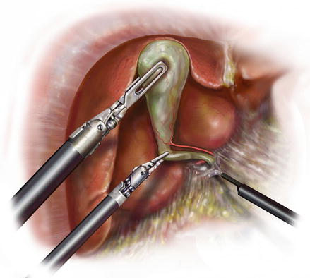
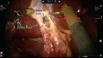
Figure 37.2
Illustration of laparoscopic cholecystectomy demonstrating exposure of the critical view
Figure 37.3
Picture of multiport robotic cholecystectomy demonstrating exposure of the critical view
Step 4
Completion of cholecystectomy. The gallbladder is dissected off of the gallbladder fossa using cautery. Hemostasis of the dissection bed is ensured, and clips are evaluated to make sure they have remained in place. The gallbladder is removed through a specimen bag. Fascia is closed.
Hepatic Resection
Langenbuch later described elective hepatectomy in 1888 [11]; liver surgery has since evolved very significantly with experience as well as with the evolution of technology. Improved knowledge of liver anatomy [12–15], advances in both surgical technique and anesthesia care [16–21], use of intraoperative ultrasound [22,23], better preoperative imaging quality, and the use of vascular stapling devices [24] as well as energy-induced hemostasis [25–27] have all contributed to improved outcomes after hepatectomy [28–30]. As a result, indications for hepatectomy have widened to include patients with certain benign diseases as well as select patients with abnormal liver function. As laparoscopic experience and technology have improved, interest in using minimally invasive techniques for liver surgery has grown with the intent to take advantage of the potential benefits as noted with laparoscopic cholecystectomy. Many groups have suggested less post-operative pain, earlier return of bowel function, decreased hospital length of stay, fewer post-operative complications, and improved cosmesis [1–3] with minimally invasive hepatectomy. Most recently, robotic technology has been used for liver resection with the first robot-assisted hepatectomy reported from Japan in 2004 [31]. Multiple centers across the world have since started to apply robotic technology to the practice of minimally invasive hepatectomy. Successful procedures have been reported, and outcomes have been comparable to the laparoscopic approach [32].
Right Hepatectomy
Step 1
The room is set up, ports are placed, the patient is positioned in reverse Trendelenberg position with the right side slightly up.
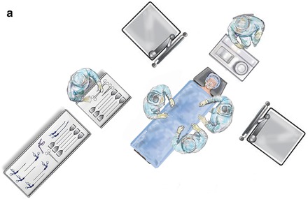
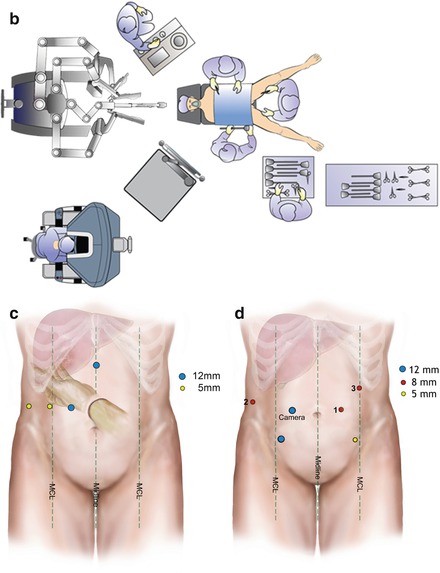
Figure 37.4
(a) Room setup for laparoscopic hepatectomy. Patient is positioned in the center of the room. Anesthesia sits at the patient’s head. Surgeons and assistant stand at either side of the operating room (OR) table. The technician stands at the surgeon’s preferred side of the table. (b) Room setup for robotic assisted hepatectomy. Patient is positioned in the center of the room in split-leg position. Anesthesia sits at the patient’s left shoulder. One surgeon and assistant stand at either side of the operating room (OR) table or between the legs. The robotic surgeon sits at the robotic console. The technician stands at the surgeon’s preferred side of the table. (c) Illustration of port placement for hand-assisted laparoscopic right hepatectomy. Note that for pure laparoscopic right hepatectomy, the hand-port can be switched for a 10–12 assist port. MCL mid clavicuar line. (d) Illustration of port placement for robotic-assisted right hepatectomy. Robotic ports for robotic instruments are represented by the 8 mm ports
Step 2
Laparoscopic dissection of ligamentous attachments of the liver.
First, the falciform ligament is dissected to the hepatic veins using cautery or a sealing device. Next, the right triangular and coronary ligaments are dissected to mobilize the right liver.
Figure 37.5
(a) Illustration of the falciform dissected. (b) The falciform is dissected. (c) Dissection is continued to the anterior surface of the hepatic veins
Figure 37.6
(a) Illustration of the triangular and coronary ligaments dissected. (b) The right lobe liver is lifted anteriorly and medially to dissect the triangular ligament
Step 3
Ultrasound the liver, map the lesion(s).
Intraoperative imaging should confirm location of the suspected lesion(s) to ensure no other unexpected lesions are present anywhere else in the liver, to ensure that the pathology suspected is resectable, and to confirm the appropriate resection plan as decided preoperatively (ie to confirm a right hepatectomy is appropriate instead of a wedge resection or trisegmentectomy).
Step 4
If robotic technology is to be used, the robot is docked now. Robotic instruments, including the robotic camera, are introduced.
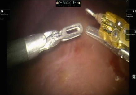
Figure 37.7
Robotic instruments are introduced
Step 5
Short hepatic veins are dissected and ligated. With the liver retracted anteriorly, short hepatic veins (SHV) that return blood directly from the liver to the IVC are dissected, ligated, and divided.
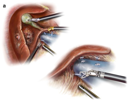
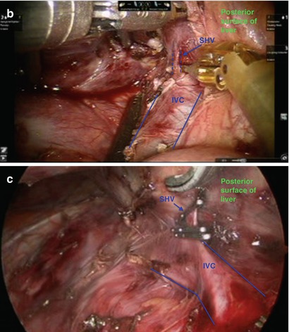
Figure 37.8
(a) Illustration of the liver retracted anteriorly, and short hepatic veins (SHV) are dissected and ligated. (b) The liver is retracted anteriorly, and short hepatic veins are dissected. (c) SHV ligated with clips. Shears are in the background to cut between clips
Step 6. Inflow Dissection
(a)
Lower the hilar plate.
To accomplish this, cholecystectomy is initiated. Please refer to cholecystectomy portion of this chapter for details. After transecting the cystic duct and artery, tissue overlying the porta hepatis is dissected at the base of the liver and toward the right, exposing the right portal structures.
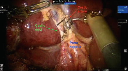
Figure 37.9
Cystic artery and duct are clipped after the critical view is identified. They will be transected, and dissection will continue along the porta
Figure 37.10
(a–c) Dissection of portal tissue at the base of the right liver leads to exposure of the right hepatic structures. The right hepatic artery is the first structure to be exposed as it is most anterolateral
(b)
Isolate, ligate, and divide the right hepatic artery
After exposing the right hepatic artery, the tissue surrounding it is further dissected to completely isolate the vessel. This includes tissue posterior to it. It is then ligated with ties and divided. Alternatively, a stapling device can be used as space allows.
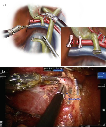
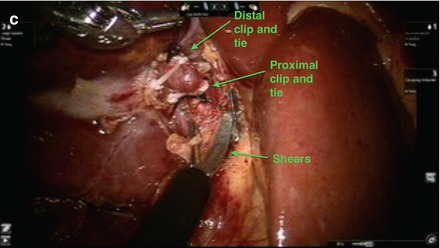
Figure 37.11
(a) Illustration demonstrating ligation and division of the right hepatic artery. (b) Tissue behind the artery is dissected with dissector. (c) Right hepatic artery is ligated with clips and ties and divided
(c)
Isolate, ligate, and divide the right portal vein.
The right portal vein (RPV) rests posterior to the right hepatic artery. It is exposed after transection of the RHA. After exposing the right portal vein (RPV), the tissue surrounding it is further dissected to completely isolate the vessel. A branch to the caudate is typically seen running laterally, and this should be ligated and divided.
Once the right portal vein is completely isolated, a silk tie can be placed around it to retract and facilitate introduction of a laparoscopic, roticulating stapler across it. The vessel is ligated and divided using the stapler.
Figure 37.12
(a) Illustration of the right portal vein (RPV) isolated, ligated, and divided. (b) The RPV is identified posterior to the RHA after the RHA is transected. (c) Branch running laterally and to the caudate is identified, isolated, and eventually ligated and divided
Figure 37.13
(a) RPV completely isolated with dissector across it posteriorly. (b) Tie around RPV helps retract and expose it optimally for introduction of stapler around it. (c) Stapler around RPV. (d) Stapled RPV
(d)
Isolate, ligate, and divide the right hepatic duct.
Note that the duct can also alternatively be ligated intrahepatically if able to help avoid injury to the left ductal system. The right hepatic duct is routinely found as the medial-most structure. It is best exposed after transection of the right hepatic artery and portal vein. After isolating the duct, it is tied distally, then cut proximally to allow visualization of bile draining from the proximal duct. This allows for definite identification of the duct. The duct is then fully transected, and additional clips are placed on the distal duct to ensure it is sealed.
Figure 37.14
(a) Illustration of the right hepatic duct (RHD) isolated. It is ligated distally and cut proximally to confirm bile from the proximal duct. Additional clips are then placed to the proximal and distal ends of the duct. (b). The RHD is exposed after transection of the right portal vein. (c) The RHD is fully dissected. (d). The RHD is ligated distally. (e) The proximal duct is cut to identify bile coming from it. (f) Additional clips are placed on the proximal and distal duct ends. (g) Cholecystectomy is completed. The gallbladder is dissected from the gallbladder fossa. It is placed in a laparoscopic bag and removed from the abdominal cavity
Outflow Dissection
The right hepatic vein can be isolated in an extrahepatic manner, as depicted below, if the tumor rests near the inferior vena cava. Alternatively, the right hepatic vein can be isolated within the hepatic parenchyma during parenchymal dissection. For extrahepatic dissection:
(a)
On the anterior surface of the liver, the right hepatic vein is dissected along its medial edge, creating a window to the undersurface of the liver.
(b)
While lifting the liver anteriorly, the right hepatic vein is dissected from the undersurface of the liver.
(c)
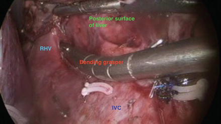
While along the undersurface of the liver, a bending grasper is placed anterior to the RHV and advanced through the window that has been created.
(d)
The liver is allowed to fall back into place, and the bending grasper is visualized from the anterior surface of the liver through the window created. A vessel loop is fed to the grasper, and the grasper gently pulls back through to the undersurface of the liver. The other end of the vessel loop is fed around the lateral border of the RHV from an anterior approach, as well. The lateral edge of the liver is retracted anteriorly again, and both ends of the vessel loops should be around the RHV, thus having a defined isolation of this vein.
(e)
The vessel loop can then retract the vein gently, acting as a guide while a stapler is introduced. The vessel is ligated and transected with a vascular loaded roticulating stapler.
Figure 37.15
The right liver is lifted anteriorly, and the right hepatic vein is dissected from the liver’s undersurface
Figure 37.16
Along the undersurface of the liver, a bending grasper is placed anterior to the RHV. It is advanced through the window created
Figure 37.17
(a) The liver is allowed to fall back into place, and the tips of the bending grasper can be seen across the anterior surface of the liver. A vessel loop is fed to this grasper. (b) The vessel loop is fully around the RHV as seen here from the undersurface of the liver. The vessel loop helps to guide the stapler across the vein
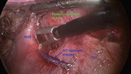
Figure 37.18
(a) The RHV is stapled from the undersurface of the liver. (b) The RHV stapled and transected. Highlighted is the distal end of the RHV on the IVC
Parenchymal Transection
Large caliber, figure of eight, stay stitches are placed on either side of the line of parenchymal transection, which should also be the “line of demarcation” that appears after inflow has been ligated. These stitches help retract the liver. The line of transection is defined using hook cautery. Ultrasound is repeated to ensure that the pathology is included within the resection specimen. The parenchyma is coagulated, and ducts/vessels are controlled with ties, clips, or staples, as appropriate. The specimen is placed in a specimen bag and removed from the abdominal cavity. Hemostasis is ensured at the resection bed, and the falciform ligament is tacked to the diaphragm.
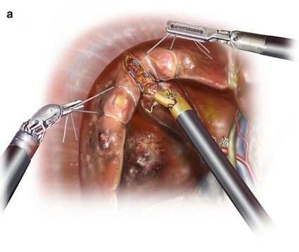
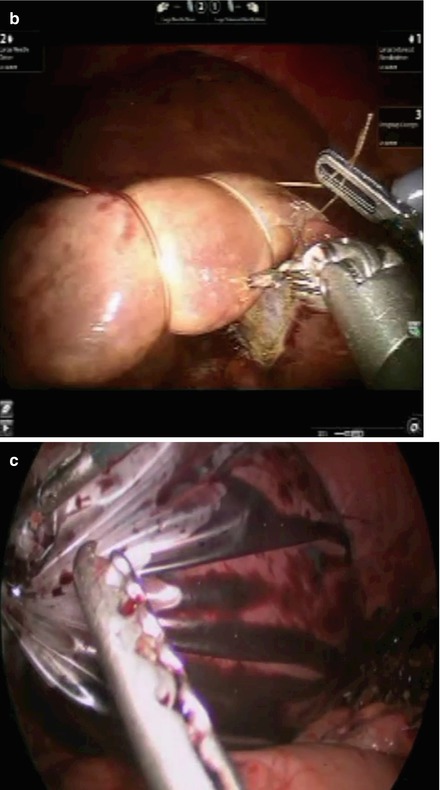
Figure 37.19
(a) Illustration of large, absorbable stitches placed on both sides of the transection line. (b) Large, absorbable stitches are placed on either side of the line of demarcation. (c) After complete parenchymal transection, specimen is placed in a specimen bag and retrieved from the abdominal cavity
Left Hepatectomy
Step 1
The room is set up similar to right hepatectomy, ports are placed, the patient is positioned in reverse Trendelenberg position with the left side slightly up.
Figure 37.20


(a) Illustration of port placement for hand-assisted laparoscopic left hepatectomy. Note that for pure laparoscopic left hepatectomy, the hand-port can be switched for a 10–12 assist port. (b) Port placement for robotic assisted left hepatectomy
Related posts:


Stay updated, free articles. Join our Telegram channel
Full access? Get Clinical Tree
