Fig. 16.1
Simplified recording circuit showing tissue voltage source V tissue, two impedances representing electrodes Z electrode1 and Z electrode2, and the input impedance of the amplifier Z amp
Definition 1
An Electrical Circuit is a closed loop pathway in which electrical current flows. The amount of current flowing is the same at every point along the circuit. The circuit must be continuous such that it is complete; an opening along the path stops current flow. The source of voltage drives a current through the circuit impedances according to Ohm’s law. In electronics, there are many types of voltage sources including constant (or DC for direct current) or alternating (or AC for alternating current). Our IOM recording circuit as shown in Fig. 16.1 has physiologic voltage sources that are alternating with a range of frequency components, designated as V tissue.
Definition 2
Impedance (usually denoted as “Z”) is the term for devices that resist the flow of electrical current. There are three basic types of impedance as described below.
Definition 3
Ohm’s law is a very simple relationship. It takes voltage (V) to drive a current through impedance (Z) to that current flow (I) according to the formula: Current = Voltage/Impedance (I = V/Z). A different way to phrase it is that current passing through impedance builds up a voltage across that impedance.
KEY POINT: When current flows in the circuits due to some voltage source such as a physiologic signal, that current builds a voltage across every location in the circuit where there is impedance.
Definition 4
A Voltage Divider explains that the source voltage divides among the impedances in the circuit. Larger impedances get a larger share of the voltage, but the sum of the voltages building on the circuit impedances always totals the exact value of the source voltage.
KEY POINT: We wish the physiologic signal to build up voltage on the amplifier input impedance where it can be amplified. We therefore need to ensure that the electrode impedances are small relative to the amplifier input impedance, as shown in Fig. 16.1 .
Definition 5
An Amplifier is an electronic circuit that multiplies an input voltage by a gain factor to deliver an output voltage. IOM equipment generally utilizes differential amplifiers in which the input voltage is the voltage difference between two inputs.
Technical Note: An ideal differential amplifier would deliver an output equal to the voltage difference across its inputs (or differential voltage) multiplied by the gain. A real-world amplifier also amplifies the voltage common to both inputs (or common mode voltage) though to a much lesser extent. The iso-ground serves as the reference point for this common mode voltage. The measure of an amplifier’s ability to reject the common mode voltage is the common mode rejection ratio (CMRR), which is the ratio of its differential gain to its common mode gain. The CMRR of modern IOM equipment can exceed 100 dB or 100,000:1.
KEY POINTS: Selection of an iso-ground location impacts common mode voltage. Furthermore, imbalances between electrode impedances result in one electrode impedance with more voltage buildup and negatively impact the CMRR of an amplifier.
Sources of electrical interference and more details have been added to the simplified recording circuit in Fig. 16.2. Notice that Z electrode2 is now shown as a complex of three different parts in parallel. This is because electrical impedance has three components, including a resistive component R, capacitive component C, and inductive component L. For simplicity, the impedance subcomponents are only shown for Z electrode2, but exist for all circuit impedances, even if just at the tiniest of levels.
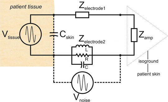
Fig. 16.2
Simplified recording circuit with potential sources of electrical interference
Electrical Impedance is a measure of the opposition to alternating current flow. It is the vector summation of three different impedance components arising from electrical resistance, electrical capacitance, and electrical inductance. This is usually reported in Ohms (Ω).
Electrical Resistance is a measure of the opposition to direct current flow. The resistive component of impedance does not change with frequency.
Electrical Capacitance is a measure of how much charge can be held. The capacitive component of impedance decreases as the frequency of flowing current (or applied voltage) increases.
Electrical Inductance is a measure of opposition to a changing current flow. The inductive component of impedance increases as the frequency of flowing current (or applied voltage) increases.
KEY POINT: The capacitive and inductive components of impedance allow nearby sources of electrical interference to couple through the air with the recording circuitry.
It is the inductive and capacitive components highlighted in Fig. 16.2 that allow for the two most common pathways for electrical interference to enter the recording circuit.
Pathway 1: The Skin of the Patient C skin
The patient’s skin has large capacitance (the ability to hold charge). It is this capacitance that allows the skin to build up large static voltages that hurt when they are discharged in the winter. This capacitance aids the skin of the patient in being an attractive antenna for electrical interference nearby. In filling the capacitance of the patient’s skin, the charge distributes all over the patient’s body surface, inherently bringing this noise to the recording electrodes in contact with the skin and into the recording circuit.
Pathway 2: Ambient Sources of Electrical Noise V noise
A source of ambient electrical interference is shown as V noise. For simplicity, it is only shown to be coupling with the impedance of leadwire 2. However, every part of the circuit is potentially susceptible. As we will see later in the chapter and in many of the videos, the leadwires as well as the patient’s skin are particularly vulnerable.
An understanding of how these two pathways enable noise to enter the recording circuit will help us consider electromagnetic coupling mechanisms discussed later.
Technical note: An essential concept in data acquisition is signal-to-noise ratio (SNR ) . We can think of any of the recordings as a combination of two elements. The first is the signal we are interested in. The remainder is what we consider to be noise. Noise is also referred to as interference or artifact and these terms are often used interchangeably. The ratio of the power of the signal to the power of the noise is the signal-to-noise ratio. The higher the signal-to-noise ratio, the more likely we are to be able to gain useful information from a recording. To achieve these results, we can increase the signal or reduce the noise.
Signal averaging is commonly used when the signal-to-noise ratio is low (e.g., auditory brainstem response where the signal has very low voltage). Averaging improves the signal-to-noise ratio by reducing the noise amplitude by virtue of the fact that the signal in each trial stimuli remains the same, but the noise varies in a random way such that averaging trials reduce the averaged noise, with the signal-to-noise ratio improving by the square root of the number of averaging trials.
While averaging represents an important way to improve signal-to-noise ratio , it does nothing to reduce actual noise. Much of what is presented in this chapter falls on the side of reducing the noise reaching the amplifiers, or else making the noise more common so it is rejected.
The Basic IOM Recording Circuit
The many recording electrodes attached to the patient are but a repetition of the same basic recording circuit many times over. Figure 16.3 shows the basic recording circuit including the instrumentation amplifier, two recording electrodes, amplifier iso-ground, and physiologic signal source (V tissue). Though the three electrodes shown are subdermal needle electrodes, other electrode types such as hydrogel surface pads, EEG cups, and longer needles may also be used in IOM settings. The concepts discussed here are pertinent regardless of the electrode type used or the IOM equipment used.
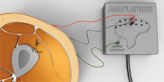
Fig. 16.3
Example of a recording scenario highlighting the basic IOM recording circuit
If the insulation covering the electrodes is removed, it becomes obvious that electrodes contain many materials, even the seemingly simple needle electrodes shown. This is depicted in Fig. 16.4.
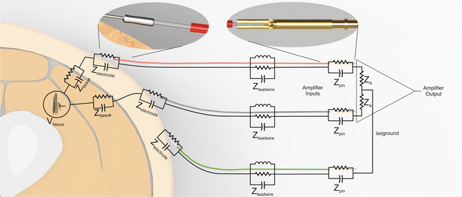
Fig. 16.4
The basic recording circuit electrical schematic showing all electrical connections in the circuit including the resistive, capacitive, and inductive components of impedance. Note the numerous dissimilar metal-to-metal connections (highlighted in the inserts)
The electrical equivalent circuit is shown in Fig. 16.4 with the exposed connections within the electrodes shown. When thinking about electrode impedance, it is common to consider the impedance of the electrode attachment to skin. However, as Fig. 16.4 shows, at many points on the circuit, we find impedance. The components of the basic recording circuit are listed under the following subheadings.
Tissue Physiologic Generator (V tissue)
The physiologic signal volume conducts in three dimensions outward from the neurogenic or myogenic source through the array of tissues surrounding it, losing amplitude exponentially as it migrates outward. A portion of the volume conducted signal electrical field conducts to each recording electrode via a near infinite number of pathways, shown in white outline, in Fig. 16.5. As a result of volume conduction losses as well as signal attenuation traveling through high impedance tissues such as adipose, by the time the physiologic signal reaches the recording electrodes, the amplitude is exponentially lower than at the source.
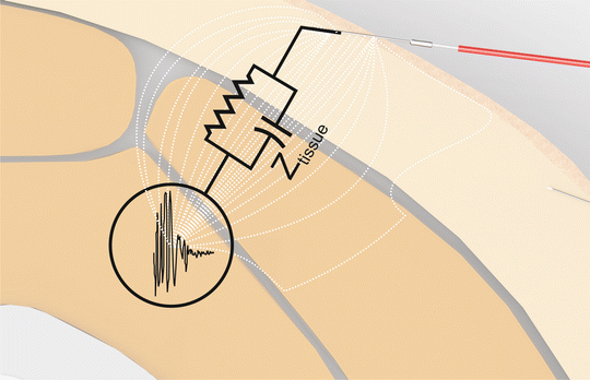
Fig. 16.5
Near infinite tissue pathways from generator to recording electrode. Current flows from the source generator to the recording electrode using a near infinite number of tissue pathways dependent on conductivity of each pathway
Circuit Component: Tissue Between Generator and Electrode (Z tissue)
The signal pathways follow the path of least impedance through the array of different tissues from source to recording electrode. Tissues like muscle, blood vessels, capillary beds, and mucosa have low impedance (below 1 kΩ) [1]. Skin can range in impedance depending on location on the body, thickness, and concentration of sweat and sebaceous glands (typically over 40 kΩ) [1]. Tendon, fat, and bone have the highest impedances though these layers also represent unavoidable pathways to current flow if surface or subdermal needles are used. Note that many of the pathways shown from the source to the recording electrode are surprising, as they may follow unexpected pathways as shown by the far right signal path in Fig. 16.5. These multiple parallel pathways can be considered as an equivalent impedance, shown in black outline in the figure (pathways) and labeled Z tissue . There is no typical value of Z tissue , as the adipose layer thickness in the patients varies dramatically.
KEY POINT: Since tissue impedance is frequency dependent, we can assume that the different fundamental frequency components of physiologic signals will attenuate differently when volume conducted through tissue and that is indeed the case. Higher frequency signal components volume conduct through tissue with more amplitude loss on average than lower frequency signal components. Note that this tissue-filtering effect occurs prior to the signal reaching the recording electrodes!
Circuit Component: Electrode Connection to the Patient + Electrode Components (Z electrode)
Electrode connection to patient: This portion of impedance is due to the connection of the electrode with the patient’s tissue. This is typically the impedance many IOM clinicians first think of when asked what their impedances are and why care is usually taken to lower this impedance by attention to skin preparation and electrode placement.
Due to the high impedance of the epidermis, particularly the stratum corneum, it is necessary to either prepare the skin surface by some form of debridement or to use electrodes that bypass this high impedance layer such as needle electrodes. Exact levels of impedance achieved vary depending on skin preparation and surface area of electrode used, but may be anywhere between a few hundred ohms and 10 kΩ or more. The electrode conductor in contact with patient tissue has the ability to hold charge, therefore it is important to consider this portion of impedance to be a resistance in parallel with a capacitance. Needless to say, it is best to avoid dissimilar electrode types in one amplifier circuit to minimize impedance imbalance between electrodes.
Electrode components at the patient end of the electrode: Excellent volumes have been published detailing patient attachment electrodes for recording and stimulating physiologic signals [2]. Mention of a few details pertinent to the discussion is warranted.
Electrode patient connections may contain many different materials, whether biocompatible metal, conductive plastic, ionically rich hydrogel, carbon or metal foils, glues, solders, and a large list of other possible materials. In the subdermal needles shown, a medical grade stainless steel needle is soldered to a 19-strand tinned copper wire, so many different metals are present in this tiny junction. When placed together to form the patient attachment end of the electrodes, the contribution to impedance is quite low, typically less than a few ohms. However, where there are dissimilar metals, it is possible to have a voltage generated through galvanic corrosion mechanisms, the same reaction used to create voltages in many batteries. All that is needed is ionic fluid to bath the metal-to-metal junction. Ionic fluids such as sweat are readily present around the operating room bed. Any such galvanic voltage generated is added to the recording circuit as electrical interference.
KEY POINT: To avoid metal-to-metal galvanic corrosion voltages contaminating the recording circuit, care should be taken to avoid accidentally bathing the electrode and hub in fluids.
Circuit Component: The Wire Between the Electrode Patient End and Connector End (Z leadwire)
The leadwire may have many different types of conductor covered by an electrical insulating material. Some examples of conductors include multistrand tinned copper, copper, carbon fiber, and tinsel wire. Though the leadwire generally has less than a few ohms of impedance, this portion of the recording circuit plays a large role in electromagnetic interference through the inductive and capacitive components of impedance .
NOTE: Though all portions of the basic recording circuit have an inductive component of impedance, for simplicity, only the inductive component of impedance of the leadwire has been shown in Fig. 16.4 .
Circuit Component: Leadwire connection to safety connector + Electrode to amplifier connection ( Z pin )
Related posts:
 Deep Brain Stimulation
 Intraoperative Neurophysiologic Monitoring During Surgery for Supratentorial Mass Lesions
 Surgery for Chiari Type I Malformation
 Intraoperative Neurophysiological Monitoring for Intracranial Aneurysm Surgery
 Trigeminal Microvascular Decompression
 Monitoring of Jugular Venous Oxygen Saturation
Stay updated, free articles. Join our Telegram channel

Full access? Get Clinical Tree


