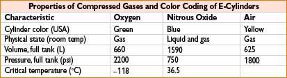
• O2 & Air: Pressure gauge reading reflects the volume of gas in the E-cylinder
Boyle’s: O2 gauge = 300 psi → liters O2 left = 660 L × (300 psi/2200 psi) = 90 L
“Fudge” [psi × 0.3]: O2 gauge = 300 psi → liters O2 left = (300 psi × 0.3) = 90 L
• N2O: If liquid N2O remains, pressure = 750 psi → weigh tank to assess N2O volume
Liters of N2O in tank = (N2O tank weight in grams/44 g) × 0.5 L
Only N2O gas in tank (∼25% N2O left) → pressure falls <750 psi → calc per Boyle’s
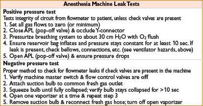
ANESTHESIA MACHINE (*SEE APPENDIX B FOR CHECKOUT RECOMMENDATIONS)
BREATHING CIRCUIT: CONNECTS ANESTHESIA MACHINE TO PATIENT
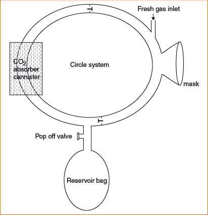
Circle system—most commonly used; prevents rebreathing of exhaled CO2 (see Fig. 3-1)
Reservoir bag:
• Reserve gas volume
Oxygen analyzer:
• Measures inspired/expired O2.
Adjustable pressure limiting valve (APL or pop-off valve):
• Can be adjusted to facilitate manual bag compression to assist ventilation of pt’s lungs.
• Allow venting of excess gas to waste scavenging system.
Bag/ventilator switch:
• Exclude/include reservoir bag & APL from system.
Inspiratory one-way valve:
• Open during inspiration & closed during expiration.
• Prevents expiratory gas from mixing with fresh gas in inspiratory limb.
Expiratory one-way valve:
• Open during expiration & closed during inspiration
• Gas is then either vented through APL valve or passes to CO2 absorber CO2 absorbent: Removes CO2 from breathing circuit (chemical neutralization)
• Most common absorbent = soda lime (Ca, Na, K-OH, & H2O)
CO2 + H2O → H2CO3
H2CO3 + 2NaOH → Na2CO3 + 2H2O + heat
Na2CO3 + Ca(OH)2 → CaCO3 + 2NaOH
Spirometer:
• Measures exhaled tidal volume & respiratory rate
Circuit pressure gauge:
• Measures circuit airway pressure in cm H2O
Figure 3-1. A circle system.
Closed-Circuit Anesthesia
• Use of FGFs exactly equal to the uptake of oxygen and anesthetic agents
• Requires (1) very low FGF, (2) total rebreathing of exhaled gases after absorption of carbon dioxide by CO2 absorber, (3) closed APL or ventilator relief valve
• Advantages: ↑ heat & humidification of gases; less pollution & agent use; cost savings
• Disadvantages: Inability to rapidly change agent concentration; may provide hypoxic/hypercarbic mix; anesthetic overdose from excessive agent concentration
Airway Pressures
• Airway pressure = airway resistance + alveolar pressure (i.e., chest & lung compliance)
• PIP = highest pressure in circuit during inspiration
• Plateau pressure = pressure during inspiratory pause (only measuring compliance)
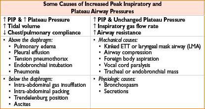
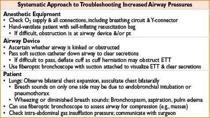
Management of Increased Airway Pressures
Open Breathing Systems (Historical, not Typically Used in Modern Medicine)
• Insufflation: Blowing of anesthetic gas across pt’s face
• Open-drop anesthesia: Volatile anesthetic dripped onto gauze-covered mask on pt’s face
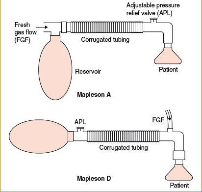
Mapleson Breathing Circuits A to E: Five Systems Described in 1950s
• Differ in fresh gas inflow tubing, mask, reservoir bag & tubing, & expiratory valve locations
• Characterized by (1) no valves directing gases to & from pt, (2) no CO2 neutralization
• Mapleson A circuit = most efficient for spontAneous ventilation (see Fig. 3-2)
• (FGF = minute ventilation, which is sufficient to prevent CO2 rebreathing)
• Mapleson D circuit = most efficient for controlleD ventilation
• (FGF forces alveolar gas away from pt & toward pressure release valve)
Bain Circuit: Modification of Mapleson D
• Fresh gas supply runs coaxially inside corrugated expiratory tubing
• Advantages: Compact, portable, easy scavenging, exhaled gases warm inhaled gases
• Disadvantages: Risk of kinking/disconnect of coaxial tubing (i.e., fresh gas inlet)
PATIENT MONITORS
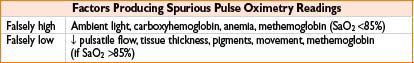
Pulse Oximetry
• Noninvasive, continuous means of assessing arterial O2 saturation
• Two light-emitting diodes @ 660 nm (absorbed by Hb) & 940 nm (O2Hb), & photoreceptor
• SaO2 = O2Hb% & Hb% are calculated from ratio of light absorbed at photoreceptor
• Accuracy is unaffected by fetal hemoglobin, sickle hemoglobin, and polycythemia
Figure 3-2. Mapleson A and D breathing apparatuses.
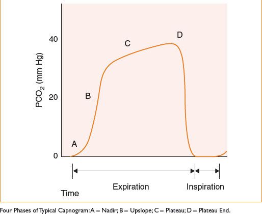
Capnography
• Continuous visual display of exhaled CO2 waveform; relies on two assumptions:
• All CO2 is a product of tissue metabolism
• PaCO2 (arterial) is 5–10 mm Hg > PACO2 (alveolar) ≈ ETCO2
• Provides the following information:
• Adequacy of ventilation & perfusion
• Presence of airway obstruction @ equipment malfunction (based on waveform)
• Positioning of double-lumen tubes (via separate capnometers to each lumen)
• Causes of abrupt ETCO2 decreases:
• Esophageal intubation
• Kinked, obstructed, or disconnected airway or gas sampling line
• Low cardiac output (e.g., pulmonary embolism, cardiac arrest)
• Causes of abrupt ETCO2 increases:
• Hypoventilation
• Hyperthermia (including malignant)
• Rebreathing (e.g., incompetent unidirectional valve, exhausted absorbent)
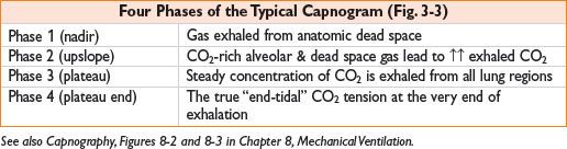
Figure 3-3. Typical capnogram.
ELECTRICAL SAFETY IN THE OR
Electrosurgery
• Surgical diathermy: High frequency alternating current to cut/cauterize blood vessels
• Electrosurgical units (ESUs) generate high-frequency current; tip of small electrode → through pt → out large electrode (dispersion pad)
• Malfunction of dispersion pad: Inadequate contact/conducting gel/disconnect
• Current will exit pt through alternate path (ECG pads, OR table) & may burn pt
• Bipolar electrodes limit current propagation to a few millimeters
• ESU may interfere with pacemaker & ECG recordings
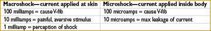
Risk of Electrocution
• Contact with two conductive materials at different voltage potentials may complete circuit & result in electric shock
• Leakage current is present in all electrical equipment
• Fibrillation threshold at skin is 100 milliamps (above leakage current magnitude)
• Current as low as 100 microamps applied directly to heart may be fatal
Ungrounded Power & Protection from Electric Shock
• Isolation transformer: Isolates OR power supply from ground potential
• If live wire contacts grounded pt, isolation transformer prevents current flow to pt
• Line isolation monitors (LIMs): Monitors how well power supply is isolated from ground
• Alarm sounds if unacceptable current flow to ground becomes possible
• Alarm does not interrupt power unless ground leakage circuit breaker activated
• Isolated power circuits do not protect against microshock
• Note: New building codes no longer required ORs to have ungrounded power
< div class='tao-gold-member'>


