Emergency Bedside Ultrasound Basics
Deciding on the type of ultrasound machine to obtain for your emergency department depends on balancing the cost versus the features desired on the machine.
Early portable ultrasound units had the advantages of low cost and user-friendly interfaces with limited adjustment options. Small viewing screens were problematic, and multiple probes could not be used simultaneously. Image quality was reduced but battery power and rapid power-up allowed immediate imaging.
Traditional, larger ultrasound machines commonly used by radiologists are designed for the radiology suite, where patients are brought to the machine. There are obvious disadvantages in bringing these to the patient bedside in a crowded emergency department, and many have a prolonged power-up period causing a delay in image acquisition. The cost of these machines is also prohibitive in most emergency departments.
Ultrasound machines designed specifically for bedside applications are now available. Small physical profiles, digital storage, fast power-up, multiple probe ports, and high-quality images are made possible by technological advances. Basic features ideal for the emergency department setting are listed in Table 6–1.
|
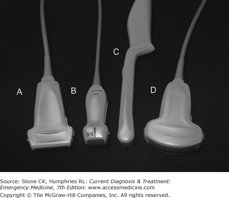
There are three main types of ultrasound probes or transducers: curved, linear, and phased array (Figure 6–1). Curved probes are used for abdominal and obstetric imaging. Linear probes are used for soft tissue and small parts imaging. Phased array probes use computer control to “bend” the ultrasound beam from a flat, small footprint to a wider pie-shaped wedge distally. This is usually called the “cardiac” probe but is also excellent to image between ribs and is often used for abdominal imaging.
Many ultrasound probes allow for use of variable frequencies. Curved array probes used for abdominal imaging, for example, may have settings from 2.5 to 5 MHz. Soft tissue probes and intracavitary/transvaginal probes may allow for settings above 7 MHz. There is an inverse relationship between the resolution of a probe and its penetration.
Most emergency departments will require a minimum of three probes, depending on the types of ultrasound examinations and procedures anticipated (Table 6–2): one for abdominal imaging, one for high-resolution shallow imaging, and an intracavitary probe. While more probes would seem beneficial, the probes make up a large portion of the cost of the system and expenditures for extra or specialty probes are unlikely to be justified.
| Examination/Procedure | Probe Type |
|---|---|
| FAST exam | Curved array 2.5–5.5 MHz or phased array 2.5–5.5 MHz |
| Enhanced FAST exam | Curved array 2.5–5.5 MHz or phased array 2.5–5.5 MHz plus linear small parts probe 5–10 MHz |
| Aorta, gallbladder | Curved array 2.5–5.5 MHz or phased array 2.5–5.5 MHz |
| Cardiac | Phased array 2.5–5.5 MHz or curved array 2.5–5.5 MHz |
| Transabdominal OB | Curved array 2.5–5.5 MHz or phased array 2.5–5.5 MHz |
| Transvaginal OB | Curved array intracavitary probe |
| Peritonsillar abscess | Curved array intracavitary probe |
| Central line guidance | Linear small parts probe 5–10 MHz |
| Foreign body | Linear small parts probe 5–10 MHz |
The American Medical Association’s (AMA) policy on ultrasound states that specialty societies should determine what constitutes proficiency for their members, and recommends that hospital medical staff base credentialing on those specialty guidelines. The American College of Emergency Physicians (ACEP) policy agrees with the AMA policy and adds that emergency physicians “should possess appropriate training and hands-on experience to perform and interpret limited bedside ultrasound imaging.” The Accreditation Council for Graduate Medicine Education (ACGME) considers ultrasound a key procedural competency for emergency medicine residents.
There is currently no universally accepted certification process for bedside ultrasound. ACEP’s guidelines for basic competency recommend 150 proctored examinations performed during emergency medicine residency plus scheduled didactic sessions, or a 16- to 24-hour course with combined didactic and hands-on training for a practice-based pathway.
Some emergency physicians have obtained certification from the American Registry for Diagnostic Medical Sonography. This requires either a continuous, 12-month training program in clinical sonography (eg, ultrasound fellowship) or documentation of ultrasound training in residency and the performance of 800 ultrasound examinations, and passage of a two-part written examination.
There are proponents for a standardized certification process for ultrasound in emergency medicine, and others who believe that emergency ultrasound is simply a technological extension of the physical examination, the use of which should not be limited. Supporters of the last can point to use of the EKG, slit lamp, and fiber optics as examples of “specialty” tools adopted by emergency physician to facilitate patient care.
Ultrasound is a mechanical wave propagated through a medium at frequency above 20,000 Hz. Diagnostic ultrasound generally uses frequencies from 2.5 to 10.5 MHz. The ultrasound waves are generated by the application of electrical current to piezoelectric crystals in the ultrasound transducer (probe). The wave then propagates through tissue, reflecting a portion of the energy back to the probe at each change in tissue density, until all of the energy in the wave is lost through reflection, refraction, or absorption. The reflected waves again contact the piezoelectric crystals that generate a small electric current that is analyzed by a computer processor. The data are then translated onto the display screen.
The amount of ultrasound energy reflected depends on the differences in density (and “stiffness” or bulk modulus) at each tissue interface. Great differences in density, such as between bone and tissue or air and tissue, cause virtually all of the ultrasound wave to be reflected back to the probe. This prevents ultrasound imaging beneath lung tissue, gas-filled bowel, or bone.
The depth to which ultrasound will penetrate depends on the frequency. The higher the frequency, the better the resolution but the distance from the skin you can image is reduced. Lower-frequency probes are used for deep abdominal imaging while higher-frequency probes are used to give high-resolution images of shallow structures.
The concept of using the lowest power setting possible to obtain a diagnostic image arose from the use of plain radiography and was extended to ultrasound. Early machines sometimes had both diagnostic and therapeutic capabilities; the therapeutic settings could deliver high energy levels that could potentially cause tissue damage. ALARA is an acronym for “As Low As Reasonably Achievable,” and it reminds the sonographer to set power levels (when adjustable) to the lowest level that allows proper imaging. There have been no substantiated reports of fetal injury or tissue damage with the use of modern diagnostic ultrasound.
Ultrasound can produce artifacts that may both aid and hinder interpretation of images. The recognition of artifact will help prevent misinterpretation of findings.
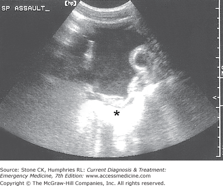
An ultrasound wave loses energy or attenuates as it passes through tissue; this is due mostly to reflection as interfaces between tissues of different density are encountered. When there are no differences in density, such as when imaging through collections of urine, blood, or other homogenous fluid, no energy is reflected. This allows more energy to arrive at the structures beneath the fluid and to reflect back to the probe. Structures underlying fluid collections will appear to be brighter (more echogenic) than other structures at the same depth (Figure 6–2).
Brightly reflective (echogenic) structures may cause reverberation artifact (also known as comet-tail or ring-down artifact). This results from ultrasound energy bouncing from the probe to a highly reflective structure, back to the probe and so on, causing the appearance of a “comet tail” trailing down away from the echogenic structure. This often occurs beneath metallic foreign bodies and air pockets (Figure 6–3).

As ultrasound waves strike a curved structure, some of that energy is reflected (or refracted, or both) away from the probe. As the angle increases, more energy is reflected away until a critical angle is reached where no part of the wave returns to the probe. This results in an apparent “shadow” at the edges of curved structures such as vessels imaged in short axis, gallbladder in short axis, etc. It is particularly important to recognize edge shadow (or “critical angle”) artifact to prevent confusion with true shadowing structures such as gallstones or foreign bodies (Figure 6–4).

The term “knobology” simply refers to the various adjustments and settings available on a particular ultrasound machine. An emergency physician working in an unfamiliar department should familiarize himself or herself with the control functions before the shift. Some machines will have slide potentiometers (also known as “time gain compensators”) that adjust the gain (brightness) at various depths while compact machines often have automatic adjustments.
At a minimum, the physician should know the position and function of the power switch, freeze, save and print controls, frequency selection toggle, and the caliper/calculation button. Every machine will have different options, so refer to your technical manual or the clinical/technical representative for your brand’s capabilities. Table 6–3 describes the function of common ultrasound machine controls and functions.
| Calculations | Used in conjunction with calipers. Calculations available generally depend on the probe being used and the type of exam; obstetric settings might allow for calculating fetal heart rate |
| Calipers | This control places one or more icons on the screen that can be moved to measure objects or select points in tracings for calculations |
| Color Doppler | Color Doppler assigns two colors to represent flow toward or away from the probe. Often used to determine blood flow in a vessel or structure |
| Depth | Depth controls the depth of field on your screen; the depth is usually measured in centimeters to the right of the monitor screen |
| Doppler | Used to determine the velocity of flow through a vessel |
| Dynamic range | Dynamic range determines how many shades of gray will be displayed between black and white. In practice, lower numbers increase contrast while higher numbers visualize subtle differences in tissue. The range available is typically 30–70 dB |
| Freeze | The freeze button “freezes” the image on the screen to allow saving, printing, or measurements |
| Harmonic imaging | Also called tissue harmonics, this function allows the incorporation of harmonic waves generated by the original ultrasound wave to allow better resolution at lower frequencies. Also tends to improve contrast |
| M-mode | “Motion” mode. A line is positioned vertically across the display; when activated, the image within the line is scrolled across the screen. Useful for calculation of fetal heart rate and measuring cardiac structures |
| On/off | Turns machine on/off |
| Power | Power is the amount of ultrasound energy sent from the probe. If this control is present, set as low as possible to achieve satisfactory images |
Ultrasound probes have a marker, either a printed dot or a raised ridge, on one side of the probe to establish probe direction. This marker will correspond to an icon on the display screen that is usually found at the top left corner (but can be reversed or inverted). By convention, the probe marker is positioned generally to the patient’s right or cephalad while imaging. This convention aids review of static images; for example, a long-axis image of the abdominal aorta will always show the proximal portion to the left of the screen. Organs should be imaged in long and short axes relative to the organ itself, but the probe marker should be kept generally to the right and/or facing cephalad.
The three axes of movement of the ultrasound probe are similar to those of an airplane: pitch, roll, and yaw. Inexperienced sonographers should move the probe in one axis at a time while attempting to image structures to avoid confusion. It is preferable to hold the probe in the dominant hand while standing to the patient’s right side facing the head.
Ultrasound requires the use of a conducting gel to eliminate air between the probe and skin. Ultrasonic medium gel is preferred but in a pinch any clear gel or in fact water or blood can be used. Sterile gel is available for ultrasound-guided procedures.
The brightness level of the screen should be set so that fluid and vessels appear black on the display screen. The frequency should be adjusted so that the highest resolution is achieved while providing adequate depth penetration.
Primary Indications
The Focused Assessment with Sonography for Trauma (FAST) examination is a multiview examination of the intra-abdominal space and heart. The goals of the FAST exam are to identify free intraperitoneal fluid or pericardial effusion. Originally designed to assess traumatic injuries, the FAST is also a useful tool for the rapid assessment of any hemodynamically unstable patient.
Four basic views comprise the FAST examination: Morison’s pouch (right upper quadrant), cardiac, splenorenal (left upper quadrant), and bladder (pelvic).
The right upper quadrant view (a.k.a. Morison’s pouch view or perihepatic view) is sensitive for the detection of free fluid and is generally the first ultrasound image learned by emergency physicians. The right upper quadrant view visualizes the right lobe of the liver, the right kidney, and the potential space that lies between them known as Morison’s pouch. Detection of intraperitoneal fluid after trauma strongly indicates significant intra-abdominal injury, and in the unstable patient is a recognized indication for immediate exploratory laparotomy. The actual visualization of solid organ injuries, that is, splenic or hepatic lacerations, is unusual with ultrasound.
To obtain the Morison’s pouch view, the probe is placed between the right 8th and 11th ribs on the mid- or anterior axillary line (Figure 6–5). Some sonographers recommend the probe be held coronal to the body but this allows interference by rib shadows; holding the probe parallel to the ribs with the probe marker pointing to the posterior axilla allows an unobstructed view. The probe is adjusted so that the right kidney is visualized (Figure 6–6). The presence of a black (anechoic) stripe between the liver and kidney indicates free intraperitoneal fluid (Figure 6–7). Care should be taken to image the subdiaphragmatic area cephalad to the liver as well. The white outline of the kidney is Gerota’s fascia; fluid between this and the kidney is not intraperitoneal and indicates renal hematoma, renal cysts, or other pathology.


Blood initially appears black on ultrasound; as it coagulates, the image “lightens” and can appear similar to tissue but the stippled appearance of renal and hepatic parenchyma is more homogenous than mixed blood and clot. As with any ultrasound view, the probe should be “panned” through the area of interest to allow the detection of subtle abnormalities. Representative views should be saved for the medical record and quality improvement review.
The cardiac view is a rapid, one-view examination of the heart specifically used to detect pericardial effusion. In the context of the FAST examination, the cardiac view is generally not meant to evaluate ejection fraction, wall motion abnormalities, etc.
The subxyphoid view is the most commonly used cardiac view. The probe is placed under the xyphoid process almost horizontal with the floor and aimed directly under or slightly left of the sternum; the probe marker should face the patient’s right side (Figure 6–8). The probe should be adjusted so that the right and left ventricles are visualized in long axis (Figure 6–9). The display screen should show a portion of the liver at the top, followed in order by the right ventricle, intraventricular septum, and the left ventricle. A black stripe surrounding the myocardium indicates a pericardial effusion (Figure 6–10). Tiny amounts of fluid are normal in the pericardial space but these should not be visualized on ultrasound in nondependent areas. Any fluid seen in the nondependent pericardial space should be considered pathologic; however, an effusion should not always be attributed to trauma and clinical correlation is required, particularly in patients with chronic renal failure. Cardiac tamponade is a clinical syndrome; when evidence of right heart collapse during diastole is present on ultrasound, it is referred to as “imminent tamponade.”


Related posts:


Stay updated, free articles. Join our Telegram channel

Full access? Get Clinical Tree


