Aortic valve replacement (AVR) is the most common valve replacement procedure and the second most common cardiac operation following coronary artery bypass grafting (CABG) in the United States. Intraoperative transesophageal echocardiography (TEE) alters the surgical plan in 13% of patients undergoing aortic valve surgery.1 Furthermore, a consensus statement from the American College of Cardiology, American Heart Association, and American Society of Echocardiography gave intraoperative TEE a class I designation (“evidence and/or general agreement that a given procedure or treatment is useful and effective”) in patients undergoing surgical repair of valvular lesions.2 Thus, a comprehensive TEE evaluation of the aortic valve should be performed in all patients, particularly those undergoing aortic valve procedures.
Intraoperative transesophageal echocardiography is utilized to evaluate aortic valve anatomy, valve function, and hemodynamics. A comprehensive exam includes an evaluation of valvular architecture using two- (2D) and three-dimensional (3D) imaging techniques. Stenotic and regurgitant valvular lesions and their associated hemodynamic perturbations are assessed with pulsed-wave and continuous-wave Doppler echocardiography. TEE evaluation of left ventricular function and ventricular filling yields accurate and rapid assessment in patients with altered left ventricular compliance due to long-standing aortic valve pathology. The immediate post-bypass examination provides rapid assessment of the adequacy of the valve repair/replacement and any associated cardiac complications. Intraoperative examination thus aids surgical decision making, and is especially helpful in determining the feasibility of aortic valve repair versus aortic valve replacement.
A thorough understanding of the anatomy and function of the aortic valve apparatus is necessary to obtain the optimal benefit from transesophageal echocardiographic interrogation of the aortic valve. The aortic valve apparatus is comprised of the left ventricular outflow tract (LVOT), valve cusps, sinuses of Valsalva, and proximal ascending aorta (Figure 9–1). The LVOT consists of the inferior or ventricular surface of the anterior mitral leaflet, the interventricular septum, and the posterior left ventricular free wall.

A normally functioning aortic valve apparatus allows unrestricted blood flow from the left ventricle to the ascending aorta during systole and prevents retrograde blood flow from the aorta to left ventricle during diastole. Stresses during diastole are distributed across the leaflets to the commissures and into the sinuses of Valsalva. The sinuses of Valsalva also play a critical role in systole by allowing the aortic valve to open fully without contacting the walls of the aorta. Disruption in this normal anatomy or mechanisms leads to valve dysfunction. In late diastole and associated LV filling, a 12% expansion of the aortic root is observed immediately prior to aortic valve opening,3-5 which actually initiates leaflet opening prior to ventricular contraction.3,6
The proximity of the aortic valve to the upper esophagus yields detailed and high-resolution TEE images. The American Society of Echocardiography and the Society of Cardiovascular Anesthesiologists have published guidelines on obtaining the necessary tomographic views for performing a comprehensive transesophageal echocardiographic examination and are further discussed in the chapter on tomographic views (see Chapter 5). There are four recommended views for evaluation of the aortic valve.7
The midesophageal aortic valve short-axis (ME AV SAX) view permits detailed 2D, 3D and color-flow Doppler (CFD) interrogation of the aortic valve and associated root structures. The ME AV SAX view is obtained by anteflexing the TEE probe and rotating the transducer forward to between 30° and 60° in the midesophagus.7
The normal valve consists of three cusps suspended from an associated sinus of Valsalva. The cusps are of similar shape and size with fine, feathery leaflet edges that open fully, creating the appearance of an outwardly bulging equilateral triangle. During diastole the valve leaflets should close or coapt completely. The aortic valve axis is obliquely orientated to the esophageal axis with the right coronary cusp anterior and superior to the noncoronary cusp but inferior to the left coronary cusp. Two-dimensional examination in the ME AV SAX view permits evaluation of individual leaflet architecture and range of motion throughout the systolic (opening) and diastolic (closing) cycle. Since the right coronary cusp is the most anterior cusp, it is displayed below the noncoronary and left cusps on the image display (Figure 9–2). The interatrial septum attaches to the aortic wall near the noncoronary cusp, and the left main coronary artery orifice can frequently be visualized in the left coronary sinus. Thickening, calcification, commissural fusion, and decreased mobility of the leaflets are observed with valvular aortic stenosis. Bicuspid aortic valves have an eccentric circular or “fish mouth” orifice, and often a thickening or raphe that extends from the leaflet edge to the aortic wall. This raphe can be misleading in that it creates the appearance of a fused commissure, suggesting a tricuspid valve. Insertion of the leaflets to the aortic annulus differentiates a bicuspid from a tricuspid valve as the anatomic relationship between the commissures and aortic root are typically altered. Unicuspid and quadricuspid valves can also be identified easily with 2D and 3D imaging in the ME AV SAX view.
Figure 9-2.


Midesophageal aortic valve short-axis view during systole (A) and diastole (B). Note that all three aortic valve cusps are similar in size and appearance, indicating a true short-axis cross section. The aortic valve is identified by the right (R), left (L), and noncoronary (N) cusps. (LA, left atrium; LAA, left atrial appendage; RA, right atrium; IAS, interatrial septum; RVOT, right ventricular outflow tract; PAV, pulmonic valve; PA, pulmonary artery.)
The degree of valve opening can be measured by planimetry of the orifice by using the trackball and the caliper and trace functions of the machine (Figure 9–3). Although this method is simple and rapid, it is subject to error, with poor reliability between observers. Overestimation of the valve area by planimetry may occur, particularly in patients with pliable leaflets if the ultrasound beam intersects the leaflets below their tips (Figure 9–4). In addition, in many patients, the leaflets may be so calcified that the orifice cannot be identified. Color-flow Doppler in this view assesses leaflet coaptation and the severity of any associated aortic regurgitation in a semiquantitative fashion.

Figure 9-4.
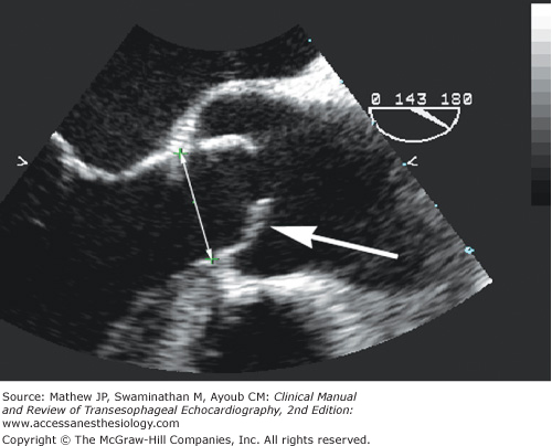
Midesophageal aortic valve long-axis view during systole demonstrating the characteristic doming of a stenotic bicuspid aortic valve with pliable leaflets (arrow). Planimetry can overestimate aortic valve area in this patient if the ultrasound beam does not intersect the leaflet tips. The annulus diameter is measured from the hinge point of one leaflet to the hinge point of the opposing leaflet during systole.
The midesophageal aortic valve long-axis (ME AV LAX) view is perpendicular to the ME AV SAX view and allows imaging of all the components of the aortic valve apparatus, including the left ventricular outflow tract, aortic valve, sinuses of Valsalva, sinotubular junction, and proximal ascending aorta. From the ME AV SAX view, the transducer is rotated forward to 120° to 150° while keeping the aortic valve in the center of view.7 A normal aortic valve appears as two thin lines that open parallel to the aortic walls during systole. The right coronary cusp, being the most anterior cusp, is displayed along the anterior surface of the aortic wall during systole (lower on the image display). The cusp seen at the top of the display is either the noncoronary or left coronary cusp depending upon probe orientation (see Figure 9–4).7
The ME AV LAX view is used to examine leaflet morphology, mobility, thickening, and calcification, and to detect subaortic pathology (eg, subaortic membrane). During systole, normal leaflets move freely, parallel to the axis of flow, and return to the plane of the annulus during diastole. Doming is the characteristic bowing appearance of the leaflets during systole as a result of calcification of the tips but not the bodies of the leaflets (see Figure 9–4). With membranous subaortic stenosis, the LVOT should be examined for the presence of a thin fibrous band or ring stretching from a hypertrophied interventricular septum to the base of the anterior leaflet of the mitral valve (MV) (Figure 9–5), which also may be thickened and stiff. Systolic anterior motion of the anterior leaflet of the MV causing dynamic LVOT obstruction in hypertrophic obstructive cardiomyopathy or after MV repair often is detected in this view. The ME AV LAX view is also used to measure the aortic annulus, sinus of Valsalva, sinotubular junction, and ascending aorta diameters when determining the appropriate size of prosthesis during valve replacement surgery. These measurements are particularly important in homograft implantations where size and geometry have tremendous implications on the success of the procedure.8 Annulus measurement in a normal valve is made from the hinge point of one leaflet to the hinge point of the opposite leaflet of the opened valve during systole (see Figure 9–4; Figure 9–6). However, in heavily diseased valves, better estimations can be made at the junction of the aortic annulus and the LVOT. To improve the estimate, multiple measurements should be made at slightly different scan angles and averaged.


Color-flow Doppler evaluation in the ME AV LAX view identifies systolic blood flow disturbances in the ascending aorta due to aortic stenosis or in the left ventricular outflow tract due to left ventricular outflow tract obstruction (LVOTO) and diastolic flow disturbances due to aortic regurgitation. M-mode measurements also can be made in the ME AV LAX view to examine leaflet mobility, thickness, and tip separation.
The transgastric long-axis (TG LAX) view is obtained by starting with the transgastric short-axis (TG SAX) view of the left ventricle at the midpapillary level and rotating the transducer forward to 90° to 110°. The mitral valve is visualized on the right side of the display in the near field while the aortic valve is displayed in the far field (Figure 9–7). The far field position of the aortic valve in this view often leads to attenuation of the ultrasound beam, thus limiting 2D imaging. However, parallel alignment of the continuous- or pulsed-wave Doppler beam through the LVOT, aortic valve, and ascending aorta is often possible and allows for the determination of velocities in the outflow tract and through the aortic valve. Acoustic shadowing in the LVOT can also be avoided using this view, making this and the deep TG LAX views invaluable in assessing prosthetic valve function.

A second view that consistently affords parallel alignment of the Doppler beam with aortic valve blood flow is the deep transgastric long-axis (deep TG LAX) view. This view is developed from the TG SAX view by advancing the probe and utilizing slight leftward flexion and anteflexion. Commonly, the probe is slowly withdrawn until the image is developed. In the deep TG LAX view, the left ventricular apex is located in the near field (top of the screen), the mitral inflow is on the right of the screen, the left atrium is located in the lower right-hand corner, and the aortic valve apparatus is seen in the lower left-hand corner of the display (far field) (Figure 9–8). As with the TG LAX view, the far-field location of aortic valve structures leads to ultrasound attenuation and 2D image degradation. Color-flow Doppler is useful during probe manipulation in order properly align the left ventricular outflow tract, aortic valve, and ascending aorta with the Doppler beam. In aortic stenosis, the continuous-wave Doppler cursor is aligned with the narrow, turbulent, high-velocity jet and the spectral Doppler display is activated. Accurate localization provides a distinctive audible sound and high-velocity (greater than 3 m/s) spectral Doppler recording that exhibits a fine feathery appearance and a midsystolic peak. Planimetry of the spectral envelope yields the velocity-time integral (VTI) and an estimate of mean aortic valve gradient. Transgastric velocity measurements obtained with Doppler imaging correlate well with data obtained by both transthoracic echocardiography (TTE) and cardiac catheterization.9

Skill and practice are necessary to obtain the deep transgastric long-axis and transgastric long-axis views. Stoddard et al demonstrated a significant increase in successful deep transgastric image acquisition with increasing experience (53% feasibility in the first 43 patients, 88% feasibility in the latter 43 patients).10
Normal aortic valve area is 3 to 4 cm2.11 Obstruction of LVOT flow into the ascending aorta can occur at three distinct anatomical sites: valvular, subvalvular, or supravalvular. Valvular obstruction is discussed in this chapter with a brief introduction to dynamic subvalvular obstruction, while subvalvular and supravalvular obstruction is discussed in the chapters on cardiomyopathies (see Chapter 14) and congenital heart disease (see Chapter 18). Valvular obstruction accounts for the vast majority of LVOT obstruction and is therefore the primary focus of this chapter.
The most common cause of aortic stenosis in the United States is calcific aortic stenosis of the elderly (Figure 9–9), followed by congenital abnormalities, including bicuspid and rarely unicuspid or quadricuspid valves (Figure 9–10). Bicuspid aortic valves account for approximately 50% of the aortic valve replacements performed in the United States and Europe, while progressive calcification of a tricuspid valve accounts for the remainder.12 The mechanism of aortic stenosis in the elderly and in congenital cases is distorted flow through the diseased valve leading to degenerative changes in the cusps, which predisposes the valve to calcification. The rate of calcification and stenosis varies widely, although elderly men with associated coronary artery disease and individuals with a history of smoking, hypercholesterolemia, and elevated serum creatinine levels demonstrate a more rapid disease progression.13-15 Many experts believe that the development of aortic stenosis is an active process, which involves chronic inflammation fueled by atherosclerotic risk factors.16 An infrequent cause of aortic stenosis in the United States is rheumatic disease, which produces commissural fusion; however, rheumatic disease remains a common cause of aortic stenosis worldwide.


Calcific aortic stenosis of the elderly characteristically occurs in patients greater than the age of 65, while patients between the ages of 35 and 55 with aortic stenosis typically have a congenital bicuspid aortic valve. Four percent of the elderly U.S. population has significant aortic stenosis,17 and approximately 1% to 2% of the population has a bicuspid aortic valve.18 Patients with a bicuspid aortic valve may also have coarctation of the aorta, dilation of the aortic root, or aortic dissection. In patients with a bicuspid aortic valve, aortic root dilation can develop irrespective of hemodynamics and age, and has been shown to continue after valve repair, suggesting a common developmental defect.19 Concomitant replacement of the ascending aorta should be considered if the ascending aortic diameter is greater than or equal to 4.5 cm, given the tendency for progressive aortic root dilation even after aortic valve replacement.20
The European Association of Echocardiography and the American Society of Echocardiography recently published guidelines and standards regarding the echocardiographic assessment of valve stenosis.11 Methods graded as appropriate and recommended for all patients (level 1) with aortic stenosis (AS) include measurement of:
- AS jet velocity
- Mean transaortic gradient
- Valve area by continuity equation (utilizing velocity-time integrals)
Methods considered reasonable when additional information is needed in select patients (level 2) include:
- Simplified continuity equation (utilizing maximum velocities)
- Velocity ratio or dimensionless index
- Aortic valve area planimetry
Two-dimensional imaging of a stenotic aortic valve in the ME AV SAX and ME AV LAX views will typically demonstrate leaflet restriction, calcification, commissural fusion, and failed leaflet coaptation. The ME AV SAX view can be used for measuring the aortic valve orifice area by planimetry, which has been shown to correlate well with other quantitative methods,21 but is also subject to error in the presence of highly pliable or heavily calcified leaflets.22 A cross section that is oblique or inferior to the leaflet tips overestimates the orifice size (see Figure 9–4). It is important, therefore, to develop an image with the smallest orifice size to ensure that the imaging plane transects the leaflet tips. To do so, the aortic valve is first imaged in the ME AV LAX, and the smallest orifice seen on the long axis is centered on the image display screen. The transducer position is then stabilized within the esophagus as the multiplane angle is rotated backward to the short-axis view. In a true short-axis cross section, the valve should appear relatively circular and all three cusps appear equal in shape. Planimetry for aortic valve area is a level 2 recommendation by expert consensus and is considered reasonable when additional information is needed in selected patients.11
The ME AV LAX view provides imaging of the left ventricular outflow tract, aortic valve, and aortic root, and is useful in differentiating valvular from subvalvular and supravalvular pathology. Reduced leaflet separation and doming with the curvature towards the aortic wall are sufficient for the qualitative diagnosis of aortic stenosis. Maximal cusp separation of less than 8 mm in a long-axis view suggests critical stenosis, whereas greater than 12 mm separation suggests noncritical disease.23 Measurements of aortic valve separation can be made with M-mode techniques where a characteristic “box car” pattern is seen on M-mode display when the aortic valve is open, with leaflet separation represented by the width of the box car. In patients with membranous subaortic stenosis, M-mode assessment may show early systolic closure of the valve (Figure 9–11).

The primary echocardiographic technique used to quantify the severity of aortic stenosis is Doppler echocardiography for determination of pressure gradient and aortic valve area. Valvular stenosis produces a decrease in pressure distal or downstream from the stenosis. This pressure gradient or pressure drop across the valve stenosis is proportional to the velocity of flow as described by the Bernoulli equation:
ΔP = 4 (V22 − V12)+ Local Acceleration + Viscous Losses
Where ΔP = Pressure gradient (mm Hg)
V2 = Velocity of flow (m/s) distal to the stenosis (aortic valve)
V1 = Velocity of flow (m/s) proximal to the stenosis (LVOT)
Given that local acceleration is only significant for long tubular lesions, and viscosity losses are only important when hematocrit is extremely high, these factors can be disregarded in clinical practice. Typically, V1 or the LVOT velocity is less than 1 m/s and therefore can be disregarded as well. This yields the commonly applied simplified Bernoulli equation:
ΔP = 4 (V2)2
ΔP = 4 (VAortic Valve)2
When V1 exceeds 1.5 m/s (eg. LVOT flow acceleration or obstruction), the modified Bernoulli equation should be utilized:
ΔP = 4 (V22 – V12)
V1 is commonly elevated in the presence of aortic regurgitation, volume overload, or other high output states. Failure to use the modified Bernoulli equation in these conditions when LVOT velocity exceeds 1.5 m/s will overestimate the pressure gradient and the severity of aortic stenosis.
In order to measure transvalvular blood velocity, continuous-wave Doppler (CWD) is used in either the TG LAX or deep TG LAX view. The CWD cursor is aligned with the narrow, turbulent, high-velocity jet and the spectral Doppler display is activated. Accurate localization provides a distinctive high-velocity (>3 m/s) spectral Doppler recording that exhibits a fine feathery appearance and a midsystolic peak (Figure 9–12). Planimetry of the spectral envelope yields the velocity-time integral and an estimate of mean aortic valve gradient. The mean gradient is a derived measurement obtained by all ultrasound systems by averaging the instantaneous gradients over the entire ejection period. The peak pressure gradient (also provided by all ultrasound systems) can be estimated from the peak velocity measurement using the simplified Bernoulli equation:
Peak Aortic Valve Pressure Gradient (PGAV) = 4 (Aortic Valve Velocity)2
Figure 9-12.
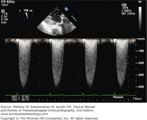
Continuous-wave spectral Doppler velocities through a stenotic aortic valve. The fine feathery appearance of the high velocities with a mid-systolic peak indicates flow through a stenotic aortic valve. The denser lower velocities near the baseline indicate flow through the left ventricular outflow tract.
Peak gradients are calculated from velocity information and therefore do not provide additional clinical information in comparison to peak velocity. A peak velocity greater than 4 m/s and a mean gradient greater than 40 mm Hg are suggestive of severe aortic stenosis (Table 9–1).
Indicator | Mild | Moderate | Severe |
|---|---|---|---|
Peak jet velocity (m/s) | <3.0 | 3.0-4.0 | >4.0 |
Mean gradient (mm Hg) | <20 | 20-40 | >40 |
Valve area (cm2) | 1.5 | 1.0-1.5 | <1.0 |
Dimensionless index | >0.50 | 0.25-0.50 | <0.25 |
Indexed AVA (cm2/m2) | >0.85 | 0.60-0.85 | <0.6 |
Related posts:


Stay updated, free articles. Join our Telegram channel

Full access? Get Clinical Tree


