Advanced Ultrasound-Guided Needle Technology
Steven L. Orebaugh
Arvind Murthy
Kristin Odenko Ligda
Richard Zhu
Paul E. Bigeleisen
Iwan Sofjan
Ultrasound-guided techniques have become the sTandard of practice in regional anesthesia. Multiple studies have shown that using ultrasound improves both the practicality and the efficacy of performing most types of nerve blocks. One imporTant feature that the ultrasound provides is needle tip visibility, which may lead to fewer complications and a more accurate anesthetic application than the traditional nerve stimulation technique. As such, various innovations have been developed in the hopes of maximizing needle visibility. These technologies, which will be discussed in the following text, include echogenic needles, needle guides, guidance positioning system (GPS)-guided needles, and digital-enhancement software.
Echogenic needle
General Concepts
The visibility of an object imaged with ultrasound depends on how well it reflects the incoming ultrasound wave back to the probe sensors. Snell’s law requires that the angle of incidence (insonation) equals the angle of reflection (backscattering) for a flat, hard surface. Thus, maximal reflection occurs when the direction of wave is perpendicular to the reflecting surface (Fig. 10.1A). By convention, this angle of insonation is defined as zero. With linear probes, the needle shaft must be parallel to the surface of the probe in order to get a strong reflection from the surface of a smooth needle. In clinical practice, this does not occur because the angle of insonation usually varies from 20 to 70 degrees when ultrasound-guided nerve block is performed. In layman’s terms, when the probe is flat on the skin, the needle usually makes an oblique angle with the surface of the probe (Fig. 10.1B). When this occurs, the sound wave is not reflected back to the probe.
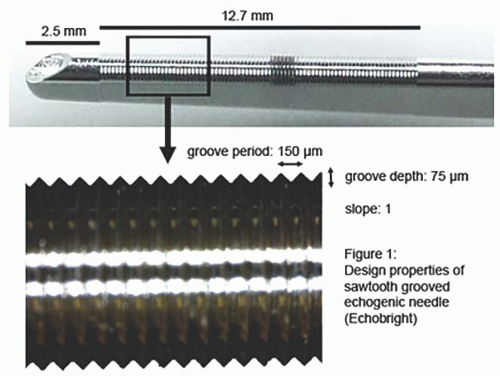
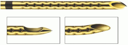
In contrast, an echogenic needle has an engraved pattern in the needle shaft that maximizes ultrasound wave reflection back toward the probe. Two types of echogenic etchings are in common use. The first type is a dihedral groove etched into the needle surface (Fig. 10.2A). This type of etching works well if the incoming wave is a plane wave aligned with the shaft of the needle. In most cases, the groove is etched continuously around the shaft of the needle similar to that of the thread on a screw (Fig. 10.3). In this manner, the dihedral reflector actually becomes a universal three-dimensional surface reflector. The depth and period of the groove can be manufactured to optimize the reflection from sound waves of different frequencies. The other type of reflector is a tetrahedral reflector that has a four-sided intermittent etching in the shaft of the needle (Fig. 10.2B). In this case, the tetrahedral etching is the universal three-dimensional reflector, and the needle has a triangular pattern etched in its surface (Fig. 10.4).
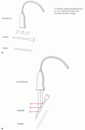 Figure 10.1. A: Drawing of an ultrasound beam perpendicular to needle. B: Drawing of an ultrasound beam oblique to needle. |
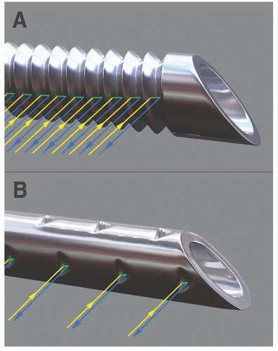 Figure 10.2. A: Dihedral echogenic etching in the needle. B: Tetrahedral echogenic etching in the needle. |
Examples of Echogenic Needles
1. Life-Tech EchoBright
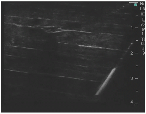
The Life-Tech EchoBright has a continuous dihedral V-shaped groove etched in its surface (Fig. 10.3). This design has been shown to produce a consTant, even intensity of reflection when the angle of insonation varies over a range from 0 to 80 degrees (Fig. 10.4). It is also available in an insulated model so that it can be used with an electrostimulator.
2. Pajunk Sonoplex
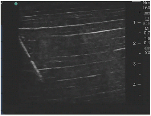
The Pajunk Sonoplex echogenic needle has a linear pattern of tetrahedral reflectors that are spaced out circumferentially around the shaft (Fig. 10.5). This arrangement allows reflection and imaging at a wide range of insertion angles and bevel orientation (Fig. 10.6). Similar to a sTandard insulated block needle, the Sonoplex can be connected to a nerve stimulator and can be used for a single injection application or continuous infusion. Several different tip heads are also available, as shown in Figure 10.5.
Clinical Data
Clinical trials comparing echogenic needles against sTandard needles are still few and far between. In general, studies show that echogenic needles have better visibility,1,2


Stay updated, free articles. Join our Telegram channel

Full access? Get Clinical Tree


